


Back to Top
SKETCH TO CAD GUIDELINES
How to Start Measuring a Part
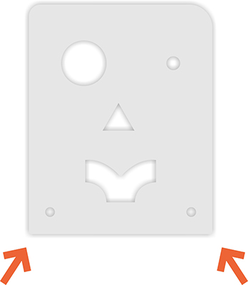
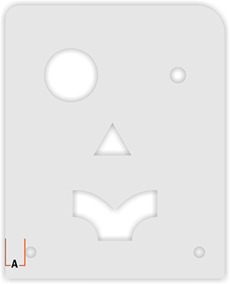
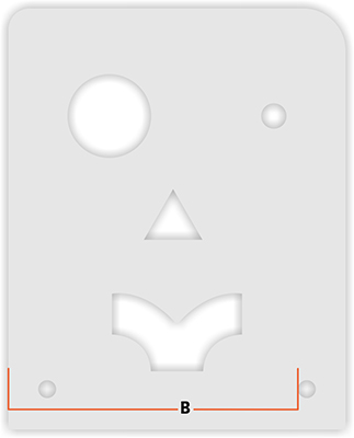
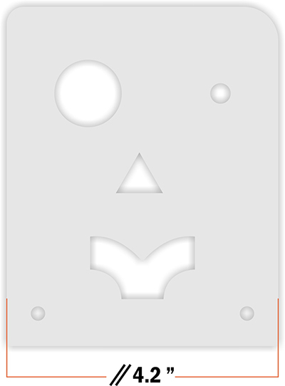
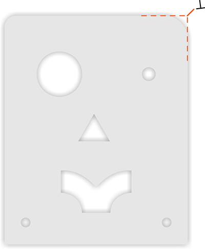
Typically, the best practice when measuring a part is to choose an area with clear and easy-to-measure features. In the example part, either of the lower corners would work well, while the upper corners would be difficult to measure from due to their rounded shape
CRITICAL DIMENSIONS AND STACK TOLERANCE
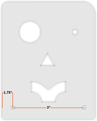
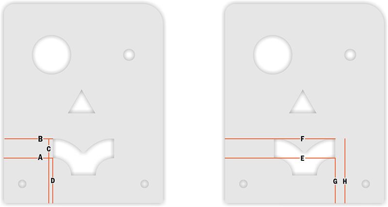
Before adding dimensions to your drawing(s), it is important to identify the critical dimensions and consider how to manage stack tolerances between features. For instance, in the example part, the distance between the holes is more crucial than their position relative to the edge. When this is the case, the part should be dimensioned accordingly, as shown here.
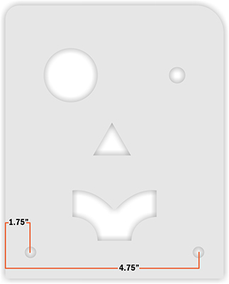
If the distance between the holes is less critical than their distance from the edge, the part should be dimensioned as shown here
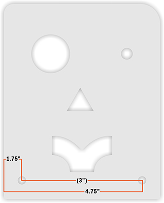
It is okay to provide redundant measurements. When doing so, place the dimension in parentheses, as shown in the image. There is no such thing as having too much information, as long as it isn't conflicting!
HOW TO KNOW WHEN YOU HAVE ENOUGH MEASUREMENTS
Once you start dimensioning a drawing, it can be difficult to stop. It's always better to have too many measurements than not enough.
One of the fundamental rules in GD&T (Geometric Dimensioning and Tolerancing) is to avoid double annotation of any feature.
If you’ve already defined the location and diameter of a hole, you don’t need to include the radius as well. Similarly,
if the start and stop points of a line are defined, the length of that line does not need to be specified.
When annotating a drawing, especially by hand, it's important to know when to stop for clarity's sake.
Even basic parts may require several drawings to avoid overcrowding with dimensions.
We prefer working with multiple clear drawings rather than one or two that are hard to decipher.
Adding redundant dimensions to a drawing is always acceptable, but please put non-critical dimensions
in parentheses.
If you miss a dimension, no worries! Our Design Services team will reach out to you via email with any questions
about your part.
HOW TO MEASURE A HOLE USING A DIGITAL MICROMETER/CALIPER
Measuring a hole accurately is crucial for both design and reverse engineering.
To accurately measure a hole, use the top (smaller) end of your caliper and open the teeth against the inner walls of the hole. Carefully keep the caliper straight and rotate the part while looking for the largest number. That number will be the diameter of the hole.
HOW TO MEASURE FROM THE EDGE OF A PART TO
THE CENTER OF A HOLE
Measuring the location of a hole can be tricky, but careful checking and a bit of math can make it quick and accurate
The first step is to measure the distance from the edge of the part to the edge of the hole (A), followed by the distance from the center of the
hole to the edge of the part (B). You can check your work by adding the radius of the hole (half of the diameter) to measurement (A); this sum
should equal measurement (B). The location of a hole should always be shown at its center point.
MEASURING THE DISTANCE BETWEEN TWO HOLES
Measuring the distance between two holes is similar to measuring a single hole. Whenever possible, measure both hole locations from the same side of the part. Never assume that the diameters of the holes are identical; measure each hole to ensure the design’s accuracy.
Use measurement A+ the radius of the hole (half of the diameter) to determine the center point of the first hole.
Use measurement B+ the radius of the hole to determine the center point of the second hole.
Subtracting the first hole’s center point measurement from the second hole’s center point measurement will give you the distance between the holes, regardless of their diameter. Remember, the location of a hole should always be shown at the center point of the circle.
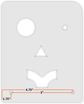
In scenarios like this, the measurement provided is considered the critical dimension. If the center-to-center dimension is crucial to your part, list that dimension and show the edge-to-center of hole dimensions in parentheses.
HOW TO MEASURE A SQUARE PART ACCURATELY
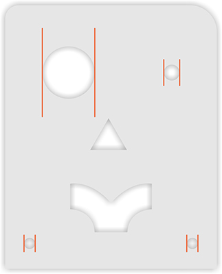
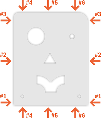
Measuring a square part is straightforward, but the process may reveal that the part isn’t perfectly square. If your part isn’t square and this isn’t caught early on, it can affect dimensions across the entire part. The easiest way to check for squareness is to measure the part in several locations. If measurement #3 is consistently different from #1, your part has an angle somewhere!
HOW TO MEASURE A COMPLICATED SHAPE
Measuring a square part is straightforward, but the process may reveal that the part isn’t perfectly square. If your part isn’t square and this isn’t caught early on, it can affect dimensions across the entire part. The easiest way to check for squareness is to measure the part in several locations. If measurement #3 is consistently different from #1, your part has an angle somewhere!
Features like the one in the image can generally be broken down into segments and approached individually. Consider each point in the design where a laser would stop, slow down, or change direction. These points are where another dimension is needed to accurately draw the design. Approach the segments of the feature as numbered in the image.
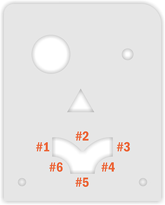
For areas #1, #3, and #5, we can locate two dimensions for the beginning and the end of each line. These dimensions can be taken from the left side and the bottom of the design, as shown below. Only the point locations are required; knowing the angle of the line is not necessary.
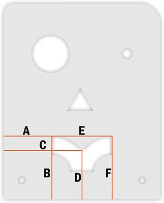
To define areas #2, #4, and #6, there are two approaches. If the geometry is a true arc with a consistent radius, only the start, stop, and highest/lowest point need to be defined. If the geometry is not a true arc, point locations along the shape are needed to connect into a continuous line. For a continuous line that changes directions, we need a point for the start, stop, and highest/lowest points of each direction. In the image below, assume the arc is not a true arc.
The points collected create a roadmap for the geometry to follow. In these scenarios, it is advisable to collect as many points as
reasonably possible while ensuring that the data is accurate. Inaccurate dimensions can result in a 'bumpy' curve rather than a smooth one.
HOW TO MEASURE AND INDICATE A RADIUS OR FILLET
Measuring a rounded edge on an existing part can be challenging, but most designers use common numbers when designing.
For instance, you are more likely to find a 0.375” radius than one that is 0.368”. Also, consider the origin of the part's design:
while 0.236” isn’t common in SAE measurements, a 6 mm radius is quite common in metric systems, as it is a whole number.
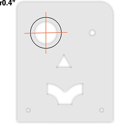
Measuring a radius on an existing part can be as simple as locating and measuring the point where the arc starts to deviate from a straight edge. The measurement taken from one side of the corner should match the measurement from the other side. If possible, mark the area (using painter’s tape works well) and measure the intersection of the two points. This will give you the radius of the corner, which can be indicated by using 'r' before your number. In the image below, the intersection points are marked in red, with the whole circle that the radius would be part of shown in black.
HOW TO INDICATE HOLE DIAMETERS ON A DRAWING

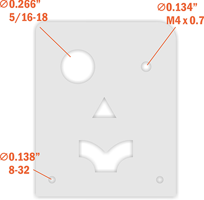
Indicate holes using the ⌀ symbol. As we do not currently offer 3D machining,
depth or 'Thru' designations are not required.
HOW TO INDICATE POST-CUTTING SERVICES
When specifying additional services for your part, please remember that we need to adhere to our available sizes and parts list,
even though we are designing your part for you.
Tapping
Tapping, like standard holes, is only offered in a 2D format. We tap through the entire part only. You can find a list of materials and thicknesses that we tap, as well as available thread sizes, here
When indicating a tapped hole, simply draw a line to the hole with text indicating the diameter and tap size. There is no need to add 'thru' or depth to the annotations.
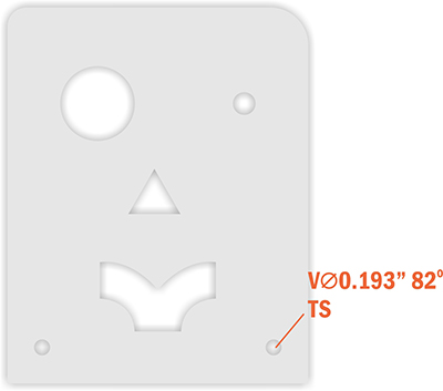
Countersinking
Countersinking is indicated by the 'Minor' (smaller) hole diameter only; the 'Major' (larger) hole diameter will be automatically set by our systems and does not need to be included. To specify countersinking, include either 'CSK' followed by the diameter and countersink angle, or 'V' followed by the minor diameter and countersink angle. Additionally, indicate which side of the part to countersink by using 'TS' for this side or 'BS' for backside. You can find our list of available countersinks here. Please note that we cannot add multiple services to a single hole (e.g., we cannot tap and countersink the same hole)
Hardware
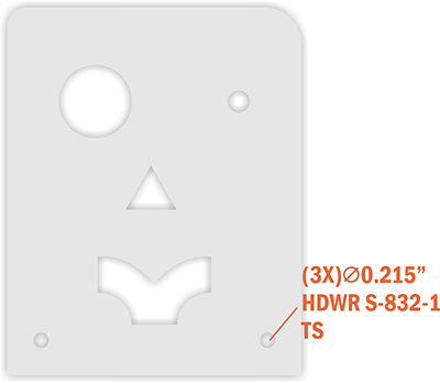
Typically, hardware is detailed in a table on a technical drawing and shown in a 3D perspective view of the part. While we don't expect you to create a table for your drawings, we do ask that you include the following three things:
- A line pointing to the hole with the desired ⌀ diameter
- The letters 'HDWR' followed by the SKU of the desired hardware
The side from which the hardware should be inserted, denoted by 'TS' for this side and 'BS' for back side.
The SKU and required hole diameter for each piece of hardware can be found in our Hardware Catalog
If you have several holes of the same size that require the same hardware, you can start your hardware callout with the number of similar instances in the drawing. For example, if you have three holes in a part that all need the same hardware, you can save time and effort by calling out your hardware as shown below. However, if only two of the three same-size holes require hardware, it's best to note them individually to avoid confusion.
HOW TO INDICATE BENDS ON YOUR DRAWINGS
There are two ways to indicate bending on a part.
1. Flat pattern with specified bend definitions
2. Bent part with outside dimension definitions
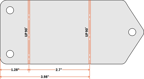
Flat Pattern
If you already know exactly where you need your bends on a flat part, you can add them to a flat-pattern drawing. Be sure to indicate the angle and direction (up or down) of each bend.
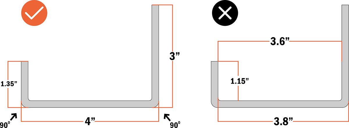
OUTER FLANGE DIMENSIONS
If you don’t know the bend deductions, bend radius, or K-factor for your bends, that’s OK! We’ve got you covered. We’ll need a side view of the part showing the desired outside dimensions of the flanges and the desired angles. Flanges are the parts of your design that will be bent, while the stationary part is typically called the base. It is important to include outside dimensions for each flange on your part. Please see the images below for examples of proper and improper bent part annotation.
DIMENSIONING CONSIDERATIONS FOR BENT PARTS
To ensure a smooth process for bent parts, consider the following dimensioning practices. It's best to dimension cut features from a fixed edge rather than from the inside of a bend. This is because the distance between the inside of a bend and a part’s edge will change depending on the materials and thicknesses used. By dimensioning your features from a fixed point, they will be where you expect them to be regardless of material or thickness changes. Ideally, cut features for each flange should be dimensioned from their nearest fixed point parallel to the bend line
PARALLELISM AND PERPENDICULARITY
The goal of annotation is to provide the designer with as much information as possible without lengthy descriptions. Parallelism and perpendicularity symbols are excellent methods for quickly and easily conveying this information. Typically, engineering drawings will include these symbols followed by tolerance and datum specifications. Fortunately, our cut tolerances for each material are already defined on our Materials Pages. This means you only need to supply the symbols, and our lasers will handle the rest
Parallelism
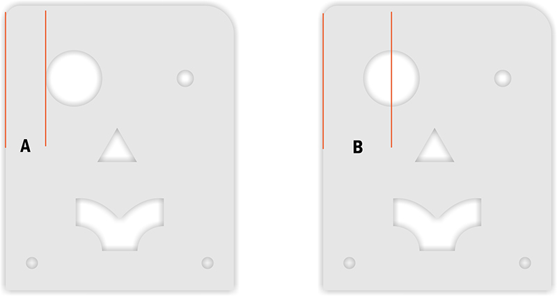
You can use the parallelism symbol to indicate that two lines run perfectly parallel to each other. There's no need to create a new leader line for this symbol; you can add it as a prefix to your dimension. While parallelism symbols are not required, they are helpful.
Perpendicularity
This symbol is used in various ways in traditional GD&T annotation, but we've simplified it for our purposes. The perpendicularity symbol is often used to define the allowable draft or runout on a feature's surface, but we've already taken care of that for you. Here, we'll use it only to define features that are perpendicular to each other in a two-dimensional environment. Like the parallelism symbol, this one isn't required, but there's no such thing as too much information! To denote perpendicularity, simply add a line pointing to the intersection of the two lines that form a 90° angle. There's no need to annotate every 90° corner in your drawing; in the example below, the parallelism and single perpendicularity symbol constrain this shape to have four 90° corners.
Materials Available for Laser Cutting

Validate your login