

Back to Top
Services available for 5052 H32 Aluminum
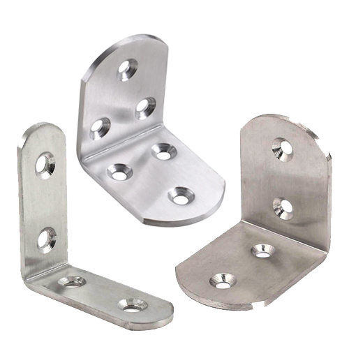
Hardware Insertion
Choose from our extensive catalog of PEM press-fit hardware, including nuts, studs, and standoffs.
Learn More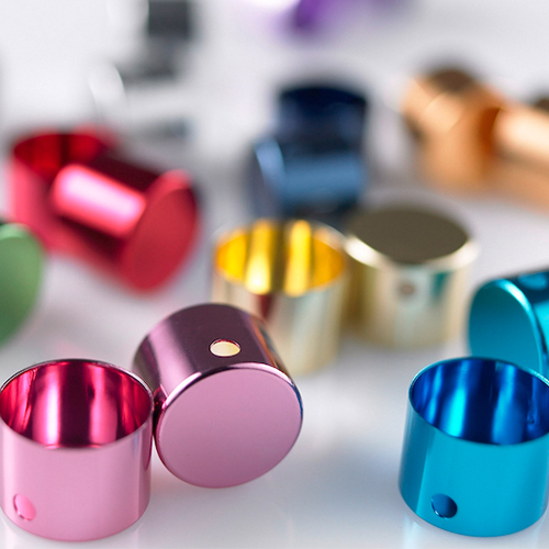
Anodizing
Our Class II anodizing services enhance the durability and aesthetic of your laser-cut parts.
Learn More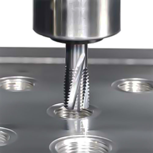
Tapping
Effortlessly incorporate threading to facilitate hardware attachments to your parts.
Learn More
Powder Coating
Enhance your laser-cut parts with a bold, durable finish and protective layer available in seven vibrant colors.
Learn More
Tumbling
Minimize surface imperfections and handling scratches commonly found in raw materials.
Learn MoreMaterial Details
.040" 5052 H32 Aluminum
- Laser Cutting View Specs
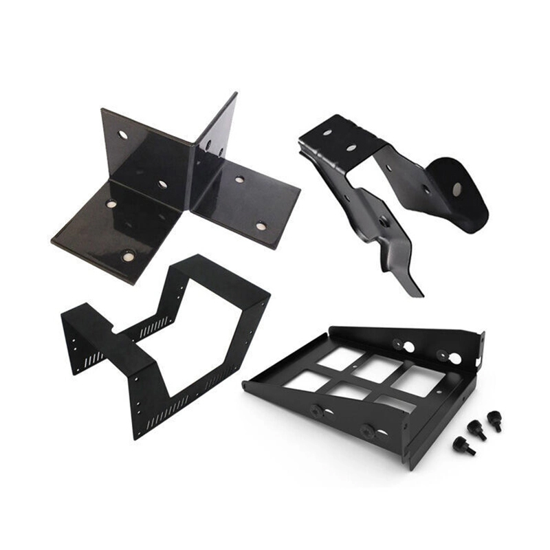
- Bending View Specs
- Hardware View Specs
| 5052 H32 Aluminum .040" General Details | INCH | MM |
|---|---|---|
| Advertised Thickness | 0.040" (1.02mm) | 1.016 mm |
| Gauge | 18 | 18 |
| Thickness tolerance positive | 0.004" | 0.1016 mm |
| Thickness tolerance negative | 0.004" | 0.1016 mm |
| Mill Finish | Cold Rolled | Cold Rolled |
| Top/Bottom finish | Identical both sides | Identical both sides |
| Sourced from | USA/Global | USA/Global |
| Laser Cutting Specification | INCH | MM |
| Cutting process | Fiber laser | Fiber laser |
| Cut tolerance +/- | 0.005" | 0.127 mm |
| Flatness tolerance before cutting | +/-0.030 per foot | +/-0.030 per foot |
| Min part size | .25″ x .375″ | 6.35 x 9.525 mm |
| Max part size | 44″ x 30″ | 1117.6 mm x 762 mm |
| Min hole size | .015″ | 0.381 mm |
| Min bridge size | .020″ | 0.508 mm |
| Min hole to edge distance | .020 | 0.508 mm |
 |
||
| Tab and slot tolerance | .010" | 0.254 mm |
 |
||
| Bending Specifications | INCH | MM |
| Min Bend Part Size | .375" x 1.5" | 9.525 mm x 38.1 mm |
| Max bending flat part size | 44″ x 30″ | 1117.6 x 762 mm |
| Max Bend Length | 44″ | 1117.6 mm |
| Min Flange Length (Before Bend/Flat Pattern) 90° or less (obtuse) | 0.255″ | 6.477 mm |
| Min Flange Length (After Bend) 90° or less (obtuse) | 0.286" | 7.2644 mm |
| Minimum Length Center of bend line 91-130* (Acute) | 0.332" | 0.332 mm |
| Die Width | 0.472″ | 11.989 mm |
| Effective Bend Radius @ 90° | 0.024″ | 0.6096 mm |
| Max Bend Angle | 130° | 130° |
| Bend angle tolerance (bend length up to 24″) | +/- 1 degree | +/- 1 degree |
| Bend angle tolerance (bend length over 24″) | +/- 2 degrees | +/- 2 degrees |
| Bend Deduction @ 90° | 0.062″ | 1.5748 mm |
| K Factor | 0.45 | 0.45 |
| Bend Relief Depth | 0.084″ | 2.1336 mm |
| Minimum Joggle Bend line to bend line @90° Max Flange | 0.363" | 9.2202 mm |
| Maximum Joggle Bend line to bend line @90° Max Flange | 3.750″ | 95.25mm |
| Dimple Specifications: Comming Soon | INCH | MM |
| Min dimple part size | 1.200" x 5.200" | 30.48 x 132.08 mm |
| Max dimple part size | 26" x 56" | 660.4 x 1422.4 mm |
| Smallest dimple | .500" | 12.7 mm |
| Largest dimple | 3.000" | 76.2 mm |
| Hardware Specifications | INCH | MM |
| Min hardware part size | 1″ x 1.5″ | 25.4 x 38.1 mm |
| Max hardware part size | 36″ x 46″ | 914.4 x 1168.4 mm |
| Minimum distance from center of bend to center of hardware insertion hole (measured from flat pattern) | .408″ | 10.3632 mm |
| Max 4 sided box flange height (hardware | 3" | 76.2 mm |
| Hardware specific specifications | Please view our Hardware Catalog | Please view our Hardware Catalog |
| 5052 H32 Aluminum .040" Properties | INCH | MM |
| Material Composition | Aluminum (Al): 95.8 – 97.7 Magnesium (Mg): 2.2 – 2.8 Chromium (Cr): 0.15 – 0.35 Iron (Fe): 0 – 0.4 Silicon (Si): 0 – 0.25 Manganese (Mn): 0 – 0.1 Zinc (Zn): 0 – 0.1 Copper (Cu): 0 – 0.1 Residuals: 0 – 0.15 | Aluminum (Al): 95.8 – 97.7 Magnesium (Mg): 2.2 – 2.8 Chromium (Cr): 0.15 – 0.35 Iron (Fe): 0 – 0.4 Silicon (Si): 0 – 0.25 Manganese (Mn): 0 – 0.1 Zinc (Zn): 0 – 0.1 Copper (Cu): 0 – 0.1 Residuals: 0 – 0.16 |
| Density | 169.344 lb/ft^3 | 169.344 lb/ft^3 |
| Heat treatments process | N/A | N/A |
| ASTM | B209-14 | B209-14 |
| Tensile Strength (Ultimate) | 34 ksi | 34 ksi |
| Tensile Strength (Yield) | 26 ksi | 26 ksi |
| Shear Strength | 20 ksi | 20 ksi |
| Shear Modulus | 3700 ksi | 3700 ksi |
| Fatigue Strength | 17 ksi | 17 ksi |
| Brinell Hardness | 60 | 60 |
| Elongation at Break | 12% | 12% |
| Elastic Modulus | 9900 ksi | 9901 ksi |
| Poisson’s Ratio | 0.33 | 1.33 |
| Thermal Conductivity | 138 BTU/h-ft °F | 139 BTU/h-ft °F |
| Melting Point | 1120 °F | 1121 °F |
| Magnetic | No | No |
| Does it Rust | No | No |
.063" 5052 H32 Aluminum
- Laser Cutting View Specs
- Bending View Specs
- Plating View Specs
- Powder Coating View Specs
- Anodizing View Specs
- Hardware View Specs
- Tapping View Specs
| 5052 H32 Aluminum .063" General Details | INCH | MM |
|---|---|---|
| Advertised Thickness | 0.063" | 1.6002 mm |
| Gauge | 14 | 14 |
| Thickness tolerance positive | 0.004" | 0.1016 mm |
| Thickness tolerance negative | 0.004" | 0.1016 mm |
| Mill Finish | Cold Rolled | Cold Rolled |
| Top/Bottom finish | Identical both sides | Identical both sides |
| Sourced from | USA/Global | USA/Global |
| Laser Cutting Specification | INCH | MM |
| Cutting process | Fiber laser | Fiber laser |
| Cut tolerance +/- | 0.005" | 0.127 mm |
| Flatness tolerance before cutting | +/-0.030 per foot | +/-0.030 per foot |
| Min part size | .25″ x .375″ | 6.35 x 9.525 mm |
| Max part size | 44″ x 30″ | 1117.6 mm x 762 mm |
| Min hole size | .022″ | 0.5588 mm |
| Min bridge size | .024″ | 0.6096 mm |
| Min hole to edge distance | .020 | 0.508 mm |
|
||
| Tab and slot tolerance | .010" | 0.254 mm |
|
||
| Anodizing Specifications | INCH | MM |
| Min anodizing part size | 1″ x 3″ | 25.4 x 76.2 mm |
| Max anodizing part size | 23" x 23" | 584.2 x 584.2 mm |
| Bending Specifications | INCH | MM |
| Min Bend Part Size | .375" x 1.5" | 9.525 mm x 38.1 mm |
| Max bending flat part size | 44″ x 30″ | 1117.6 x 762 mm |
| Max Bend Length | 44″ | 1117.6 mm |
| Min Flange Length (Before Bend/Flat Pattern) 90° or less (obtuse) | 0.255″ | 6.477 mm |
| Min Flange Length (After Bend) 90° or less (obtuse) | 0.303" | 7.6962 mm |
| Die Width | 0.472" | 11.9888 mm |
| Effective Bend Radius @ 90° | 0.035″ | 0.889 mm |
| Max Bend Angle | 130° | 130° |
| Bend angle tolerance (bend length up to 24″) | +/- 1 degree | +/- 1 degree |
| Bend angle tolerance (bend length over 24″) | +/- 2 degrees | +/- 2 degrees |
| Bend Deduction @ 90° | 0.096″ | 2.4384 mm |
| K Factor | 0.42 | 0.42 |
| Bend Relief Depth | 0.118″ | 2.9972 mm |
| Minimum Joggle Bend line to bend line @90° Max Flange | 0.324" | 8.2296 mm |
| Maximum Joggle Bend line to bend line @90° Max Flange | 3.750″ | 95.25mm |
| Deburring Specifications | INCH | MM |
| Min deburring part size | 1" x 5" | 25.4 x 127 mm |
| Max deburring part size | 24″ x 46″ | 609.6 x 1168.4 mm |
| Dimple Specifications: Comming Soon | INCH | MM |
| Min dimple part size | 1.200" x 5.200" | 30.48 x 132.08 mm |
| Max dimple part size | 26" x 56" | 660.4 x 1422.4 mm |
| Smallest dimple | .500" | 12.7 mm |
| Largest dimple | 3.000" | 76.2 mm |
| Hardware Specifications | INCH | MM |
| Min hardware part size | 1″ x 1.5″ | 25.4 x 38.1 mm |
| Max hardware part size | 36″ x 46″ | 914.4 x 1168.4 mm |
| Minimum distance from center of bend to center of hardware insertion hole (measured from flat pattern) | .425″ | 10.795 mm |
| Max 4 sided box flange height (hardware | 3" | 76.2 mm |
| Hardware specific specifications | Please view our Hardware Catalog | Please view our Hardware Catalog |
| Powder Coating Specifications | INCH | MM |
| Min powder coating part size | 1" x 3" | 25.4 x 76.2 mm |
| Max powder coating part size | 23" x 23" | 584.2 x 584.2 mm |
| Tapping Specifications | INCH | MM |
| Largest Tap | Oct-32 | Oct-32 |
| Smallest Tap | M2 x 0.4 | M2 x 0.4 |
| Min Flat Part Size Tapping | 0.949" x 1.5" | 24.1046 x 38.1 mm |
| Max Flat Part Size Tapping | 36" x 46" | 914.4 x 1168.4 mm |
| Tapping Min Hole to Edge | 0.032" | 0.8128 mm |
| 5052 H32 Aluminum .063" Properties | INCH | MM |
| Material Composition | Aluminum (Al): 95.8 – 97.7 Magnesium (Mg): 2.2 – 2.8 Chromium (Cr): 0.15 – 0.35 Iron (Fe): 0 – 0.4 Silicon (Si): 0 – 0.25 Manganese (Mn): 0 – 0.1 Zinc (Zn): 0 – 0.1 Copper (Cu): 0 – 0.1 Residuals: 0 – 0.15 | Aluminum (Al): 95.8 – 97.7 Magnesium (Mg): 2.2 – 2.8 Chromium (Cr): 0.15 – 0.35 Iron (Fe): 0 – 0.4 Silicon (Si): 0 – 0.25 Manganese (Mn): 0 – 0.1 Zinc (Zn): 0 – 0.1 Copper (Cu): 0 – 0.1 Residuals: 0 – 0.15 |
| Density | 169.344 lb/ft^3 | 169.344 lb/ft^3 |
| Heat treatments process | N/A | N/A |
| ASTM | B209-14 | B209-14 |
| Tensile Strength (Ultimate) | 34 ksi | 34 ksi |
| Tensile Strength (Yield) | 26 ksi | 26 ksi |
| Shear Strength | 20 ksi | 20 ksi |
| Shear Modulus | 3700 ksi | 3700 ksi |
| Fatigue Strength | 17 ksi | 17 ksi |
| Brinell Hardness | 60 | 60 |
| Elongation at Break | 12% | 12% |
| Elastic Modulus | 9900 ksi | 9900 ksi |
| Poisson’s Ratio | 0.33 | 0.33 |
| Thermal Conductivity | 138 BTU/h-ft °F | 138 BTU/h-ft °F |
| Melting Point | 1120 °F | 1120 °F |
| Magnetic | No | No |
| Does it Rust | No | No |
.080" 5052 H32 Aluminum
- Laser Cutting View Specs
- Bending View Specs
- Plating View Specs
- Powder Coating View Specs
- Anodizing View Specs
- Hardware View Specs
- Tapping View Specs
| 5052 H32 Aluminum .080" General Details | INCH | MM |
|---|---|---|
| Advertised Thickness | 0.080" | 2.032 mm |
| Gauge | 12 | 12 |
| Thickness tolerance positive | 0.005" | 0.127 mm |
| Thickness tolerance negative | 0.005" | 0.127 mm |
| Mill Finish | Cold Rolled | Cold Rolled |
| Top/Bottom finish | Identical both sides | Identical both sides |
| Sourced from | USA/Global | USA/Global |
| Laser Cutting Specification | INCH | MM |
| Cutting process | Fiber laser | Fiber laser |
| Cut tolerance +/- | 0.005" | 0.127 mm |
| Flatness tolerance before cutting | +/-0.030 per foot | +/-0.030 per foot |
| Min part size | .25″ x .375″ | 6.35 x 9.525 mm |
| Max part size | 44″ x 30″ | 1117.6 mm x 762 mm |
| Min hole size | .028″ | 0.7112 mm |
| Min bridge size | .030″ | 0.762 mm |
| Min hole to edge distance | .024 | 0.6096 mm |
|
||
| Tab and slot tolerance | .010" | 0.254 mm |
|
||
| Anodizing Specifications | INCH | MM |
| Min anodizing part size | 1″ x 3″ | 25.4 x 76.2 mm |
| Max anodizing part size | 23" x 23" | 584.2 x 584.2 mm |
| Bending Specifications | INCH | MM |
| Min Bend Part Size | .375" x 1.5" | 9.525 mm x 38.1 mm |
| Max bending flat part size | 44″ x 30″ | 1117.6 x 762 mm |
| Max Bend Length | 44″ | 1117.6 mm |
| Min Flange Length (Before Bend/Flat Pattern) 90° or less (obtuse) | 0.255″ | 6.477 mm |
| Min Flange Length (After Bend) 90° or less (obtuse) | 0.313" | 7.9502 mm |
| Minimum Length Center of bend line 91-130* (Acute) | 0.332" | 8.4328 mm |
| Die Width | 0.472" | 11.9888 mm |
| Effective Bend Radius @ 90° | 0.045″ | 1.143 mm |
| Max Bend Angle | 130° | 130° |
| Bend angle tolerance (bend length up to 24″) | +/- 1 degree | +/- 1 degree |
| Bend angle tolerance (bend length over 24″) | +/- 2 degrees | +/- 2 degrees |
| Bend Deduction @ 90° | 0.115″ | 2.921 mm |
| K Factor | 0.45 | 0.45 |
| Bend Relief Depth | 0.150″ | 3.81 mm |
| Minimum Joggle Bend line to bend line @90° Max Flange | 0.343" | 8.7122 mm |
| Maximum Joggle Bend line to bend line @90° Max Flange | 3.750″ | 95.25mm |
| Deburring Specifications | INCH | MM |
| Min deburring part size | 1" x 5" | 25.4 x 127 mm |
| Max deburring part size | 24″ x 46″ | 609.6 x 1168.4 mm |
| Dimple Specifications: Comming Soon | INCH | MM |
| Min dimple part size | 1.200" x 5.200" | 30.48 x 132.08 mm |
| Max dimple part size | 26" x 56" | 660.4 x 1422.4 mm |
| Smallest dimple | .750" | 19.05 mm |
| Largest dimple | 3.000" | 76.2 mm |
| Hardware Specifications | INCH | MM |
| Min hardware part size | 1″ x 1.5″ | 25.4 x 38.1 mm |
| Max hardware part size | 36″ x 46″ | 914.4 x 1168.4 mm |
| Minimum distance from center of bend to center of hardware insertion hole (measured from flat pattern) | .443″ | 11.2522 mm |
| Max 4 sided box flange height (hardware | 3" | 76.2 mm |
| Hardware specific specifications | Please view our Hardware Catalog | Please view our Hardware Catalog |
| Powder Coating Specifications | INCH | MM |
| Min powder coating part size | 1" x 3" | 25.4 x 76.2 mm |
| Max powder coating part size | 23" x 23" | 584.2 x 584.2 mm |
| Tapping Specifications | INCH | MM |
| Largest Tap | 1/4/2028 | 1/4/2028 |
| Smallest Tap | M2 x 0.4 | M2 x 0.4 |
| Min Flat Part Size Tapping | 0.949" x 1.5" | 24.1046 x 38.1 mm |
| Max Flat Part Size Tapping | 36" x 46" | 914.4 x 1168.4 mm |
| Tapping Min Hole to Edge | 0.040" | 1.016 mm |
| 5052 H32 Aluminum .080" Properties | INCH | MM |
| Material Composition | Aluminum (Al): 95.8 – 97.7 Magnesium (Mg): 2.2 – 2.8 Chromium (Cr): 0.15 – 0.35 Iron (Fe): 0 – 0.4 Silicon (Si): 0 – 0.25 Manganese (Mn): 0 – 0.1 Zinc (Zn): 0 – 0.1 Copper (Cu): 0 – 0.1 Residuals: 0 – 0.15 | Aluminum (Al): 95.8 – 97.7 Magnesium (Mg): 2.2 – 2.8 Chromium (Cr): 0.15 – 0.35 Iron (Fe): 0 – 0.4 Silicon (Si): 0 – 0.25 Manganese (Mn): 0 – 0.1 Zinc (Zn): 0 – 0.1 Copper (Cu): 0 – 0.1 Residuals: 0 – 0.15 |
| Density | 169.344 lb/ft^3 | 169.344 lb/ft^3 |
| Heat treatments process | N/A | N/A |
| ASTM | B209-14 | B209-14 |
| Tensile Strength (Ultimate) | 34 ksi | 34 ksi |
| Tensile Strength (Yield) | 26 ksi | 26 ksi |
| Shear Strength | 20 ksi | 20 ksi |
| Shear Modulus | 3700 ksi | 3700 ksi |
| Fatigue Strength | 17 ksi | 17 ksi |
| Brinell Hardness | 60 | 60 |
| Elongation at Break | 12% | 12% |
| Elastic Modulus | 9900 ksi | 9900 ksi |
| Poisson’s Ratio | 0.33 | 0.33 |
| Thermal Conductivity | 138 BTU/h-ft °F | 138 BTU/h-ft °F |
| Melting Point | 1120 °F | 1120 °F |
| Magnetic | No | No |
| Does it Rust | No | No |
.090" 5052 H32 Aluminum
- Laser Cutting View Specs
- Bending View Specs
- Plating View Specs
- Powder Coating View Specs
- Anodizing View Specs
- Hardware View Specs
- Tapping View Specs
| 5052 H32 Aluminum .090" General Details | INCH | MM |
|---|---|---|
| Advertised Thickness | 0.090" | 2.286 mm |
| Gauge | 11 | 11 |
| Thickness tolerance positive | 0.005" | 0.127 mm |
| Thickness tolerance negative | 0.005" | 0.127 mm |
| Mill Finish | Cold Rolled | Cold Rolled |
| Top/Bottom finish | Identical both sides | Identical both sides |
| Sourced from | USA/Global | USA/Global |
| Laser Cutting Specification | INCH | MM |
| Cutting process | Fiber laser | Fiber laser |
| Cut tolerance +/- | 0.005" | 0.127 mm |
| Flatness tolerance before cutting | +/-0.030 per foot | +/-0.030 per foot |
| Min part size | .25″ x .375″ | 6.35 x 9.525 mm |
| Max part size | 44″ x 30″ | 1117.6 mm x 762 mm |
| Min hole size | .032″ | 0.8128 mm |
| Min bridge size | .034″ | 0.8636 mm |
| Min hole to edge distance | .027 | 0.6858 mm |
|
||
| Tab and slot tolerance | .010" | 0.254 mm |
|
||
| Anodizing Specifications | INCH | MM |
| Min anodizing part size | 1″ x 3″ | 25.4 x 76.2 mm |
| Max anodizing part size | 23" x 23" | 584.2 x 584.2 mm |
| Bending Specifications | INCH | MM |
| Min Bend Part Size | .375" x 1.5" | 9.525 mm x 38.1 mm |
| Max bending flat part size | 44″ x 30″ | 1117.6 x 762 mm |
| Max Bend Length | 44″ | 1117.6 mm |
| Min Flange Length (Before Bend/Flat Pattern) 90° or less (obtuse) | 0.255″ | 6.477 mm |
| Min Flange Length (After Bend) 90° or less (obtuse) | 0.326" | 8.2804 mm |
| Minimum Length Center of bend line 91-130* (Acute) | 0.332" | 8.4328 mm |
| Die Width | 0.472" | 11.9888 mm |
| Effective Bend Radius @ 90° | 0.032″ | 0.8128 mm |
| Max Bend Angle | 130° | 130° |
| Bend angle tolerance (bend length up to 24″) | +/- 1 degree | +/- 1 degree |
| Bend angle tolerance (bend length over 24″) | +/- 2 degrees | +/- 2 degrees |
| Bend Deduction @ 90° | 0.142″ | 3.6068 mm |
| K Factor | 0.37 | 0.37 |
| Bend Relief Depth | 0.142″ | 3.6068 mm |
| Minimum Joggle Bend line to bend line @90° Max Flange | 0.354" | 8.9916 mm |
| Maximum Joggle Bend line to bend line @90° Max Flange | 3.750″ | 95.25mm |
| Deburring Specifications | INCH | MM |
| Min deburring part size | 1" x 5" | 25.4 x 127 mm |
| Max deburring part size | 24″ x 46″ | 609.6 x 1168.4 mm |
| Dimple Specifications: Comming Soon | INCH | MM |
| Min dimple part size | 1.200" x 5.200" | 30.48 x 132.08 mm |
| Max dimple part size | 26" x 56" | 660.4 x 1422.4 mm |
| Smallest dimple | 1.000" | 25.4 mm |
| Largest dimple | 3.000" | 76.2 mm |
| Hardware Specifications | INCH | MM |
| Min hardware part size | 1″ x 1.5″ | 25.4 x 38.1 mm |
| Max hardware part size | 36″ x 46″ | 914.4 x 1168.4 mm |
| Minimum distance from center of bend to center of hardware insertion hole (measured from flat pattern) | .426″ | 10.8204 mm |
| Max 4 sided box flange height (hardware) | 3" | 76.2 mm |
| Hardware specific specifications | Please view our Hardware Catalog | Please view our Hardware Catalog |
| Powder Coating Specifications | INCH | MM |
| Min powder coating part size | 1" x 3" | 25.4 x 76.2 mm |
| Max powder coating part size | 23" x 23" | 584.2 x 584.2 mm |
| Tapping Specifications | INCH | MM |
| Largest Tap | 1/4/2028 | 1/4/2028 |
| Smallest Tap | M2 x 0.4 | M2 x 0.4 |
| Min Flat Part Size Tapping | 0.949" x 1.5" | 24.1046 x 38.1 mm |
| Max Flat Part Size Tapping | 36" x 46" | 914.4 x 1168.4 mm |
| Tapping Min Hole to Edge | 0.045" | 1.143 mm |
| Tapping Min Hole Center to Material Edge | Tap hole size/2 +0.045" | Tap hole size/2 +0.045" |
| 5052 H32 Aluminum .090" Properties | INCH | MM |
| Material Composition | Aluminum (Al): 95.8 – 97.7 Magnesium (Mg): 2.2 – 2.8 Chromium (Cr): 0.15 – 0.35 Iron (Fe): 0 – 0.4 Silicon (Si): 0 – 0.25 Manganese (Mn): 0 – 0.1 Zinc (Zn): 0 – 0.1 Copper (Cu): 0 – 0.1 Residuals: 0 – 0.15 | Aluminum (Al): 95.8 – 97.7 Magnesium (Mg): 2.2 – 2.8 Chromium (Cr): 0.15 – 0.35 Iron (Fe): 0 – 0.4 Silicon (Si): 0 – 0.25 Manganese (Mn): 0 – 0.1 Zinc (Zn): 0 – 0.1 Copper (Cu): 0 – 0.1 Residuals: 0 – 0.15 |
| Density | 169.344 lb/ft^3 | 169.344 lb/ft^3 |
| Heat treatments process | N/A | N/A |
| ASTM | B209-14 | B209-14 |
| Tensile Strength (Ultimate) | 34 ksi | 34 ksi |
| Tensile Strength (Yield) | 26 ksi | 26 ksi |
| Shear Strength | 20 ksi | 20 ksi |
| Shear Modulus | 3700 ksi | 3700 ksi |
| Fatigue Strength | 17 ksi | 17 ksi |
| Brinell Hardness | 60 | 60 |
| Elongation at Break | 12% | 12% |
| Elastic Modulus | 9900 ksi | 9900 ksi |
| Poisson’s Ratio | 0.33 | 0.33 |
| Thermal Conductivity | 138 BTU/h-ft °F | 138 BTU/h-ft °F |
| Melting Point | 1120 °F | 1120 °F |
| Magnetic | No | No |
| Does it Rust | No | No |
.100" 5052 H32 Aluminum
- Laser Cutting View Specs
- Bending View Specs
- Plating View Specs
- Powder Coating View Specs
- Anodizing View Specs
- Hardware View Specs
- Tapping View Specs
| 5052 H32 Aluminum .100" General Details | INCH | MM |
|---|---|---|
| Advertised Thickness | 0.100" | 2.54 mm |
| Gauge | 10 | 10 |
| Thickness tolerance positive | 0.006" | 0.1524 mm |
| Thickness tolerance negative | 0.006" | 0.1524 mm |
| Mill Finish | Cold Rolled | Cold Rolled |
| Top/Bottom finish | Identical both sides | Identical both sides |
| Sourced from | USA/Global | USA/Global |
| Laser Cutting Specification | INCH | MM |
| Cutting process | Fiber laser | Fiber laser |
| Cut tolerance +/- | 0.005" | 0.127 mm |
| Flatness tolerance before cutting | +/-0.030 per foot | +/-0.030 per foot |
| Min part size | .25″ x .375″ | 6.35 x 9.525 mm |
| Max part size | 44″ x 30″ | 1117.6 mm x 762 mm |
| Min hole size | .035″ | 0.889 mm |
| Min bridge size | .038″ | 0.9652 mm |
| Min hole to edge distance | .030 | 0.762 mm |
|
||
| Tab and slot tolerance | .010" | 0.254 mm |
|
||
| Anodizing Specifications | INCH | MM |
| Min anodizing part size | 1″ x 3″ | 25.4 x 76.2 mm |
| Max anodizing part size | 23" x 23" | 584.2 x 584.2 mm |
| Bending Specifications | INCH | MM |
| Min Bend Part Size | .375" x 1.5" | 9.525 mm x 38.1 mm |
| Max bending flat part size | 44″ x 30″ | 1117.6 x 762 mm |
| Max Bend Length | 44″ | 1117.6 mm |
| Min Flange Length (Before Bend/Flat Pattern) 90° or less (obtuse) | 0.368″ | 9.3472 mm |
| Min Flange Length (After Bend) 90° or less (obtuse) | 0.463" | 11.7602 mm |
| Minimum Length Center of bend line 91-130* (Acute) | 0.478" | 12.1412 mm |
| Die Width | 0.630" | 16.002 mm |
| Effective Bend Radius @ 90° | 0.125″ | 3.175 mm |
| Max Bend Angle | 130° | 130° |
| Bend angle tolerance (bend length up to 24″) | +/- 1 degree | +/- 1 degree |
| Bend angle tolerance (bend length over 24″) | +/- 2 degrees | +/- 2 degrees |
| Bend Deduction @ 90° | 0.191″ | 4.8514 mm |
| K Factor | 0.4 | 0.4 |
| Bend Relief Depth | 0.245″ | 6.223 mm |
| Minimum Joggle Bend line to bend line @90° Max Flange | 0.478" | 12.1412 mm |
| Maximum Joggle Bend line to bend line @90° Max Flange | 3.750″ | 95.25mm |
| Deburring Specifications | INCH | MM |
| Min deburring part size | 1" x 5" | 25.4 x 127 mm |
| Max deburring part size | 24″ x 46″ | 609.6 x 1168.4 mm |
| Dimple Specifications | INCH | MM |
| Min dimple part size | 1.200" x 5.200" | 30.48 x 132.08 mm |
| Max dimple part size | 26" x 56" | 660.4 x 1422.4 mm |
| Smallest dimple | 1.000" | 25.4 mm |
| Largest dimple | 3.000" | 76.2 mm |
| Hardware Specifications | INCH | MM |
| Min hardware part size | 1″ x 1.5″ | 25.4 x 38.1 mm |
| Max hardware part size | 36″ x 46″ | 914.4 x 1168.4 mm |
| Minimum distance from center of bend to center of hardware insertion hole (measured from flat pattern) | .505″ | 12.827 mm |
| Max 4 sided box flange height (hardware) | 3" | 76.2 mm |
| Hardware specific specifications | Please view our Hardware Catalog | Please view our Hardware Catalog |
| Plating Specifications | INCH | MM |
| Min Plating Part Size | 1" x 3" | 25.4 x 76.2 mm |
| Max Plating Part Size | 23" x 23" | 584.2 x 584.2 mm |
| Powder Coating Specifications | INCH | MM |
| Min powder coating part size | 1" x 3" | 25.4 x 76.2 mm |
| Max powder coating part size | 23" x 23" | 584.2 x 584.2 mm |
| Tapping Specifications | INCH | MM |
| Largest Tap | 1/4/2028 | 1/4/2028 |
| Smallest Tap | M2 x 0.4 | M2 x 0.4 |
| Min Flat Part Size Tapping | 0.949" x 1.5" | 24.1046 x 38.1 mm |
| Max Flat Part Size Tapping | 36" x 46" | 914.4 x 1168.4 mm |
| Tapping Min Hole to Edge | 0.050" | 1.27 mm |
| Tapping Min Hole Center to Material Edge | Tap hole size/2 +0.050" | Tap hole size/2 +0.050" |
| 5052 H32 Aluminum .100" Properties | INCH | MM |
| Material Composition | Aluminum (Al): 95.8 – 97.7 Magnesium (Mg): 2.2 – 2.8 Chromium (Cr): 0.15 – 0.35 Iron (Fe): 0 – 0.4 Silicon (Si): 0 – 0.25 Manganese (Mn): 0 – 0.1 Zinc (Zn): 0 – 0.1 Copper (Cu): 0 – 0.1 Residuals: 0 – 0.15 | Aluminum (Al): 95.8 – 97.7 Magnesium (Mg): 2.2 – 2.8 Chromium (Cr): 0.15 – 0.35 Iron (Fe): 0 – 0.4 Silicon (Si): 0 – 0.25 Manganese (Mn): 0 – 0.1 Zinc (Zn): 0 – 0.1 Copper (Cu): 0 – 0.1 Residuals: 0 – 0.15 |
| Density | 169.344 lb/ft^3 | 169.344 lb/ft^3 |
| Heat treatments process | N/A | N/A |
| ASTM | B209-14 | B209-14 |
| Tensile Strength (Ultimate) | 34 ksi | 34 ksi |
| Tensile Strength (Yield) | 26 ksi | 26 ksi |
| Shear Strength | 20 ksi | 20 ksi |
| Shear Modulus | 3700 ksi | 3700 ksi |
| Fatigue Strength | 17 ksi | 17 ksi |
| Brinell Hardness | 60 | 60 |
| Elongation at Break | 12% | 12% |
| Elastic Modulus | 9900 ksi | 9900 ksi |
| Poisson’s Ratio | 0.33 | 0.33 |
| Thermal Conductivity | 138 BTU/h-ft °F | 138 BTU/h-ft °F |
| Melting Point | 1120 °F | 1120 °F |
| Magnetic | No | No |
| Does it Rust | No | No |
.125" 5052 H32 Aluminum
- Laser Cutting View Specs
- Bending View Specs
- Tumbling View Specs
- Countersinking View Specs
- Deburring View Specs
- Powder Coating View Specs
- Anodizing View Specs
- Hardware View Specs
- Tapping View Specs
| 5052 H32 Aluminum .125" General Details | INCH | MM |
|---|---|---|
| Advertised Thickness | 0.125" | 3.175 mm |
| Gauge | 8 | 8 |
| Thickness tolerance positive | 0.006" | 0.1524 mm |
| Thickness tolerance negative | 0.006" | 0.1524 mm |
| Mill Finish | Cold Rolled | Cold Rolled |
| Top/Bottom finish | Identical both sides | Identical both sides |
| Sourced from | USA/Global | USA/Global |
| Laser Cutting Specification | INCH | MM |
| Cutting process | Fiber laser | Fiber laser |
| Cut tolerance +/- | 0.005" | 0.127 mm |
| Flatness tolerance before cutting | +/-0.030 per foot | +/-0.030 per foot |
| Min part size | .25″ x .375″ | 6.35 x 9.525 mm |
| Max part size | 44″ x 30″ | 1117.6 mm x 762 mm |
| Min hole size | .044″ | 1.1176 mm |
| Min bridge size | .048″ | 1.2192 mm |
| Min hole to edge distance | .038 | 0.9652 mm |
|
||
| Tab and slot tolerance | .010" | 0.254 mm |
|
||
| Anodizing Specifications | INCH | MM |
| Min anodizing part size | 1″ x 3″ | 25.4 x 76.2 mm |
| Max anodizing part size | 23" x 23" | 584.2 x 584.2 mm |
| Bending Specifications | INCH | MM |
| Min Bend Part Size | .375" x 1.5" | 9.525 mm x 38.1 mm |
| Max bending flat part size | 44″ x 30″ | 1117.6 x 762 mm |
| Max Bend Length | 44″ | 1117.6 mm |
| Min Flange Length (Before Bend/Flat Pattern) 90° or less (obtuse) | 0.368″ | 9.3472 mm |
| Min Flange Length (After Bend) 90° or less (obtuse) | 0.476" | 12.0904 mm |
| Minimum Length Center of bend line 91-130* (Acute) | 0.478" | 12.1412 mm |
| Die Width | 0.630" | 16.002 mm |
| Effective Bend Radius @ 90° | 0.125″ | 3.175 mm |
| Max Bend Angle | 130° | 130° |
| Bend angle tolerance (bend length up to 24″) | +/- 1 degree | +/- 1 degree |
| Bend angle tolerance (bend length over 24″) | +/- 2 degrees | +/- 2 degrees |
| Bend Deduction @ 90° | 0.216″ | 5.4864 mm |
| K Factor | 0.44 | 0.44 |
| Bend Relief Depth | 0.270″ | 6.858 mm |
| Minimum Joggle Bend line to bend line @90° Max Flange | 0.506" | 12.8524 mm |
| Maximum Joggle Bend line to bend line @90° Max Flange | 3.750″ | 95.25mm |
| Countersink Specifications | INCH | MM |
| Min countersink part size | 1" x 4" | 25.4 x 101.6 mm |
| Max countersink part size | 14″ x 46″ | 355.6 x 1168.4 mm |
| Countersink Min Minor | .099" | 2.5146 mm |
| Countersink Max Major | .472″ | 11.9888 mm |
| Countersink Min Hole Center to Material Edge | .361" | 9.1694 |
| Deburring Specifications | INCH | MM |
| Min deburring part size | 1" x 3" | 25.4 x 76.2 mm |
| Max deburring part size | 24″ x 46″ | 609.6 x 1168.4 mm |
| Dimple Specifications: Coming Soon | INCH | MM |
| Min dimple part size | 1.200" x 5.200" | 30.48 x 132.08 mm |
| Max dimple part size | 26" x 56" | 660.4 x 1422.4 mm |
| Smallest dimple | 1.000" | 25.4 mm |
| Largest dimple | 3.000" | 76.2 mm |
| Hardware Specifications | INCH | MM |
| Min hardware part size | 1″ x 1.5″ | 25.4 x 38.1 mm |
| Max hardware part size | 36″ x 46″ | 914.4 x 1168.4 mm |
| Minimum distance from center of bend to center of hardware insertion hole (measured from flat pattern) | .517″ | 13.1318 mm |
| Max 4 sided box flange height (hardware) | 3" | 76.2 mm |
| Hardware specific specifications | Please view our Hardware Catalog | Please view our Hardware Catalog |
| Powder Coating Specifications | INCH | MM |
| Min powder coating part size | 1" x 3" | 25.4 x 76.2 mm |
| Max powder coating part size | 23" x 23" | 584.2 x 584.2 mm |
| Tapping Specifications | INCH | MM |
| Largest Tap | M10 x 1.5 | M10 x 1.5 |
| Smallest Tap | M2 x 0.4 | M2 x 0.4 |
| Min Flat Part Size Tapping | 0.949" x 1.5" | 24.1046 x 38.1 mm |
| Max Flat Part Size Tapping | 36" x 46" | 914.4 x 1168.4 mm |
| Tapping Min Hole to Edge | 0.063" | 1.6002 mm |
| Tapping Min Hole Center to Material Edge | Tap hole size/2 +0.063" | Tap hole size/2 +0.063" |
| Tumble Specifications | INCH | MM |
| Min Part Size Tumbling | 0.5″ x 1.5″ | 12.7 x 38.1 mm |
| Max Part Size Tumbling | 4″ x 7″ | 101.6 x 177.8 mm |
| 5052 H32 Aluminum .125" Properties | INCH | MM |
| Material Composition | Aluminum (Al): 95.8 – 97.7 Magnesium (Mg): 2.2 – 2.8 Chromium (Cr): 0.15 – 0.35 Iron (Fe): 0 – 0.4 Silicon (Si): 0 – 0.25 Manganese (Mn): 0 – 0.1 Zinc (Zn): 0 – 0.1 Copper (Cu): 0 – 0.1 Residuals: 0 – 0.15 | Aluminum (Al): 95.8 – 97.7 Magnesium (Mg): 2.2 – 2.8 Chromium (Cr): 0.15 – 0.35 Iron (Fe): 0 – 0.4 Silicon (Si): 0 – 0.25 Manganese (Mn): 0 – 0.1 Zinc (Zn): 0 – 0.1 Copper (Cu): 0 – 0.1 Residuals: 0 – 0.15 |
| Density | 169.344 lb/ft^3 | 169.344 lb/ft^3 |
| Heat treatments process | N/A | N/A |
| ASTM | B209-14 | B209-14 |
| Tensile Strength (Ultimate) | 34 ksi | 34 ksi |
| Tensile Strength (Yield) | 26 ksi | 26 ksi |
| Shear Strength | 20 ksi | 20 ksi |
| Shear Modulus | 3700 ksi | 3700 ksi |
| Fatigue Strength | 17 ksi | 17 ksi |
| Brinell Hardness | 60 | 60 |
| Elongation at Break | 12% | 12% |
| Elastic Modulus | 9900 ksi | 9900 ksi |
| Poisson’s Ratio | 0.33 | 0.33 |
| Thermal Conductivity | 138 BTU/h-ft °F | 138 BTU/h-ft °F |
| Melting Point | 1120 °F | 1120 °F |
| Magnetic | No | No |
| Does it Rust | No | No |
.187" 5052 H32 Aluminum
- Laser Cutting View Specs
- Bending View Specs
- Tumbling View Specs
- Countersinking View Specs
- Deburring View Specs
- Powder Coating View Specs
- Anodizing View Specs
- Hardware View Specs
- Tapping View Specs
| 5052 H32 Aluminum .187" General Details | INCH | MM |
|---|---|---|
| Advertised Thickness | 0.187" | 4.7498 mm |
| Gauge | N/A | N/A |
| Thickness tolerance positive | 0.009" | 0.2286 mm |
| Thickness tolerance negative | 0.009" | 0.2286 mm |
| Mill Finish | Cold Rolled | Cold Rolled |
| Top/Bottom finish | Identical both sides | Identical both sides |
| Sourced from | USA/Global | USA/Global |
| Laser Cutting Specification | INCH | MM |
| Cutting process | Fiber laser | Fiber laser |
| Cut tolerance +/- | 0.005" | 0.127 mm |
| Flatness tolerance before cutting | +/-0.030 per foot | +/-0.030 per foot |
| Min part size | .500″ x .750″ | 12.7 x 19.05 mm |
| Max part size | 44″ x 30″ | 1117.6 mm x 762 mm |
| Min hole size | .065″ | 1.651 mm |
| Min bridge size | .071″ | 1.8034 mm |
| Min hole to edge distance | .056 | 1.4224 mm |
|
||
| Tab and slot tolerance | .015" | 0.381 mm |
|
||
| Anodizing Specifications | INCH | MM |
| Min anodizing part size | 1″ x 3″ | 25.4 x 76.2 mm |
| Max anodizing part size | 23" x 23" | 584.2 x 584.2 mm |
| Bending Specifications | INCH | MM |
| Min Bend Part Size | .375" x 1.5" | 9.525 mm x 38.1 mm |
| Max bending flat part size | 44″ x 30″ | 1117.6 x 762 mm |
| Max Bend Length | 44″ | 1117.6 mm |
| Min Flange Length (Before Bend/Flat Pattern) 90° or less (obtuse) | 0.620″ | 15.748 mm |
| Min Flange Length (After Bend) 90° or less (obtuse) | 0.798" | 20.2692 mm |
| Minimum Length Center of bend line 91-130* (Acute) | N/A | N/A |
| Die Width | 0.984" | 24.9936 mm |
| Effective Bend Radius @ 90° | 0.250″ | 6.35 mm |
| Max Bend Angle | 90° | 90° |
| Bend angle tolerance (bend length up to 24″) | +/- 1 degree | +/- 1 degree |
| Bend angle tolerance (bend length over 24″) | +/- 2 degrees | +/- 2 degrees |
| Bend Deduction @ 90° | 0.356″ | 9.0424 mm |
| K Factor | 0.43 | 0.43 |
| Bend Relief Depth | 0.457″ | 11.6078 mm |
| Minimum Joggle Bend line to bend line @90° Max Flange | 0.826" | 20.9804 mm |
| Maximum Joggle Bend line to bend line @90° Max Flange | 3.750″ | 95.25mm |
| Countersink Specifications | INCH | MM |
| Min countersink part size | 1" x 4" | 25.4 x 101.6 mm |
| Max countersink part size | 14″ x 46″ | 355.6 x 1168.4 mm |
| Countersink Min Minor | .099" | 2.5146 mm |
| Countersink Max Major | .531″ | 13.4874 mm |
| Countersink Min Hole Center to Material Edge | .361" | 9.1694 |
| Deburring Specifications | INCH | MM |
| Min deburring part size | 1" x 3" | 25.4 x 76.2 mm |
| Max deburring part size | 24″ x 46″ | 609.6 x 1168.4 mm |
| Hardware Specifications | INCH | MM |
| Min hardware part size | 1″ x 1.5″ | 25.4 x 38.1 mm |
| Max hardware part size | 36″ x 46″ | 914.4 x 1168.4 mm |
| Minimum distance from center of bend to center of hardware insertion hole (measured from flat pattern) | .634″ | 16.1036 mm |
| Max 4 sided box flange height (hardware) | 3" | 76.2 mm |
| Hardware specific specifications | Please view our Hardware Catalog | Please view our Hardware Catalog |
| Powder Coating Specifications | INCH | MM |
| Min powder coating part size | 1" x 3" | 25.4 x 76.2 mm |
| Max powder coating part size | 23" x 23" | 584.2 x 584.2 mm |
| Tapping Specifications | INCH | MM |
| Largest Tap | 1/2/2020 | 1/2/2020 |
| Smallest Tap | Apr-40 | Apr-40 |
| Min Flat Part Size Tapping | 0.949" x 1.5" | 24.1046 x 38.1 mm |
| Max Flat Part Size Tapping | 36" x 46" | 914.4 x 1168.4 mm |
| Tapping Min Hole to Edge | 0.094" | 2.3876 mm |
| Tapping Min Hole Center to Material Edge | Tap hole size/2 +0.094" | Tap hole size/2 +0.094" |
| Tumble Specifications | INCH | MM |
| Min Part Size Tumbling | 0.5″ x 1.5″ | 12.7 x 38.1 mm |
| Max Part Size Tumbling | 4″ x 7″ | 101.6 x 177.8 mm |
| 5052 H32 Aluminum .187" Properties | INCH | MM |
| Material Composition | Aluminum (Al): 95.8 – 97.7 Magnesium (Mg): 2.2 – 2.8 Chromium (Cr): 0.15 – 0.35 Iron (Fe): 0 – 0.4 Silicon (Si): 0 – 0.25 Manganese (Mn): 0 – 0.1 Zinc (Zn): 0 – 0.1 Copper (Cu): 0 – 0.1 Residuals: 0 – 0.15 | Aluminum (Al): 95.8 – 97.7 Magnesium (Mg): 2.2 – 2.8 Chromium (Cr): 0.15 – 0.35 Iron (Fe): 0 – 0.4 Silicon (Si): 0 – 0.25 Manganese (Mn): 0 – 0.1 Zinc (Zn): 0 – 0.1 Copper (Cu): 0 – 0.1 Residuals: 0 – 0.15 |
| Density | 169.344 lb/ft^3 | 169.344 lb/ft^3 |
| Heat treatments process | N/A | N/A |
| ASTM | B209-14 | B209-14 |
| Tensile Strength (Ultimate) | 34 ksi | 34 ksi |
| Tensile Strength (Yield) | 26 ksi | 26 ksi |
| Shear Strength | 20 ksi | 20 ksi |
| Shear Modulus | 3700 ksi | 3700 ksi |
| Fatigue Strength | 17 ksi | 17 ksi |
| Brinell Hardness | 60 | 60 |
| Elongation at Break | 12% | 12% |
| Elastic Modulus | 9900 ksi | 9900 ksi |
| Poisson’s Ratio | 0.33 | 0.33 |
| Thermal Conductivity | 138 BTU/h-ft °F | 138 BTU/h-ft °F |
| Melting Point | 1120 °F | 1120 °F |
| Magnetic | No | No |
| Does it Rust | No | No |
.250" 5052 H32 Aluminum
- Laser Cutting View Specs
- Bending View Specs
- Tumbling View Specs
- Countersinking View Specs
- Deburring View Specs
- Powder Coating View Specs
- Anodizing View Specs
- Hardware View Specs
- Tapping View Specs
| 5052 H32 Aluminum .250" General Details | INCH | MM |
|---|---|---|
| Advertised Thickness | 0.250" | 6.35 mm |
| Gauge | N/A | N/A |
| Thickness tolerance positive | 0.027" | 0.6858 mm |
| Thickness tolerance negative | 0.027" | 0.6858 mm |
| Sourced from | USA/Global | USA/Global |
| Laser Cutting Specification | INCH | MM |
| Cutting process | Fiber laser | Fiber laser |
| Cut tolerance +/- | 0.005" | 0.127 mm |
| Flatness tolerance before cutting | +/-0.030 per foot | +/-0.030 per foot |
| Min part size | .500″ x .750″ | 12.7 x 19.05 mm |
| Max part size | 44″ x 30″ | 1117.6 mm x 762 mm |
| Min hole size | .088″ | 2.2352 mm |
| Min bridge size | .095″ | 2.413 mm |
| Min hole to edge distance | .075 | 1.905 mm |
|
||
| Tab and slot tolerance | .035" | 0.889 mm |
|
||
| Anodizing Specifications | INCH | MM |
| Min anodizing part size | 1″ x 3″ | 25.4 x 76.2 mm |
| Max anodizing part size | 23" x 23" | 584.2 x 584.2 mm |
| Bending Specifications | INCH | MM |
| Min Bend Part Size | .375" x 1.5" | 9.525 mm x 38.1 mm |
| Max bending flat part size | 44″ x 30″ | 1117.6 x 762 mm |
| Max Bend Length | 44″ | 1117.6 mm |
| Min Flange Length (Before Bend/Flat Pattern) 90° or less (obtuse) | 1.150″ | 29.21 mm |
| Min Flange Length (After Bend) 90° or less (obtuse) | 1.371" | 34.8234 mm |
| Minimum Length Center of bend line 91-130* (Acute) | N/A | N/A |
| Die Width | 1.575" | 40.005 mm |
| Effective Bend Radius @ 90° | 0.250″ | 6.35 mm |
| Max Bend Angle | 90° | 90° |
| Bend angle tolerance (bend length up to 24″) | +/- 1 degree | +/- 1 degree |
| Bend angle tolerance (bend length over 24″) | +/- 2 degrees | +/- 2 degrees |
| Bend Deduction @ 90° | 0.442″ | 11.2268 mm |
| K Factor | 0.42 | 0.42 |
| Bend Relief Depth | 0.520″ | 13.208 mm |
| Minimum Joggle Bend line to bend line @90° Max Flange | 1.425" | 36.195 mm |
| Maximum Joggle Bend line to bend line @90° Max Flange | 3.750″ | 95.25mm |
| Countersink Specifications | INCH | MM |
| Min countersink part size | 1" x 4" | 25.4 x 101.6 mm |
| Max countersink part size | 14″ x 46″ | 355.6 x 1168.4 mm |
| Countersink Min Minor | .099" | 2.5146 mm |
| Countersink Max Major | .656″ | 16.6624 mm |
| Countersink Min Hole Center to Material Edge | .453" | 11.5062 |
| Deburring Specifications | INCH | MM |
| Min deburring part size | 1" x 3" | 25.4 x 76.2 mm |
| Max deburring part size | 24″ x 46″ | 609.6 x 1168.4 mm |
| Hardware Specifications | INCH | MM |
| Min hardware part size | 1″ x 1.5″ | 25.4 x 38.1 mm |
| Max hardware part size | 36″ x 46″ | 914.4 x 1168.4 mm |
| Minimum distance from center of bend to center of hardware insertion hole (measured from flat pattern) | .654″ | 16.6116 mm |
| Max 4 sided box flange height (hardware) | 3" | 76.2 mm |
| Hardware specific specifications | Please view our Hardware Catalog | Please view our Hardware Catalog |
| Powder Coating Specifications | INCH | MM |
| Min powder coating part size | 1" x 3" | 25.4 x 76.2 mm |
| Max powder coating part size | 23" x 23" | 584.2 x 584.2 mm |
| Tapping Specifications | INCH | MM |
| Largest Tap | 1/2/2020 | 1/2/2020 |
| Smallest Tap | Apr-40 | Apr-40 |
| Min Flat Part Size Tapping | 0.949" x 1.5" | 24.1046 x 38.1 mm |
| Max Flat Part Size Tapping | 36" x 46" | 914.4 x 1168.4 mm |
| Tapping Min Hole to Edge | 0.125" | 3.175 mm |
| Tapping Min Hole Center to Material Edge | Tap hole size/2 +0.125" | Tap hole size/2 +0.125" |
| Tumble Specifications | INCH | MM |
| Min Part Size Tumbling | 0.5″ x 1.5″ | 12.7 x 38.1 mm |
| Max Part Size Tumbling | 4″ x 7″ | 101.6 x 177.8 mm |
| 5052 H32 Aluminum .250" Properties | INCH | MM |
| Material Composition | Aluminum (Al): 95.8 – 97.7 Magnesium (Mg): 2.2 – 2.8 Chromium (Cr): 0.15 – 0.35 Iron (Fe): 0 – 0.4 Silicon (Si): 0 – 0.25 Manganese (Mn): 0 – 0.1 Zinc (Zn): 0 – 0.1 Copper (Cu): 0 – 0.1 Residuals: 0 – 0.15 | Aluminum (Al): 95.8 – 97.7 Magnesium (Mg): 2.2 – 2.8 Chromium (Cr): 0.15 – 0.35 Iron (Fe): 0 – 0.4 Silicon (Si): 0 – 0.25 Manganese (Mn): 0 – 0.1 Zinc (Zn): 0 – 0.1 Copper (Cu): 0 – 0.1 Residuals: 0 – 0.15 |
| Density | 169.344 lb/ft^3 | 169.344 lb/ft^3 |
| Heat treatments process | N/A | N/A |
| ASTM | B209-14 | B209-14 |
| Tensile Strength (Ultimate) | 34 ksi | 34 ksi |
| Tensile Strength (Yield) | 26 ksi | 26 ksi |
| Shear Strength | 20 ksi | 20 ksi |
| Shear Modulus | 3700 ksi | 3700 ksi |
| Fatigue Strength | 17 ksi | 17 ksi |
| Brinell Hardness | 60 | 60 |
| Elongation at Break | 12% | 12% |
| Elastic Modulus | 9900 ksi | 9900 ksi |
| Poisson’s Ratio | 0.33 | 0.33 |
| Thermal Conductivity | 138 BTU/h-ft °F | 138 BTU/h-ft °F |
| Melting Point | 1120 °F | 1120 °F |
| Magnetic | No | No |
| Does it Rust | No | No |
.375" 5052 H32 Aluminum
- Laser Cutting View Specs
- Tumbling View Specs
- Countersinking View Specs
- Deburring View Specs
- Powder Coating View Specs
- Anodizing View Specs
- Hardware View Specs
- Tapping View Specs
| 5052 H32 Aluminum .375" General Details | INCH | MM |
|---|---|---|
| Advertised Thickness | 0.375" | 9.525 mm |
| Gauge | N/A | N/A |
| Thickness tolerance positive | 0.033" | 0.8382 mm |
| Thickness tolerance negative | 0.033" | 0.8382 mm |
| Top/Bottom finish | Identical both sides | Identical both sides |
| Sourced from | USA/Global | USA/Global |
| Laser Cutting Specification | INCH | MM |
| Cutting process | Fiber laser | Fiber laser |
| Cut tolerance +/- | 0.005" | 0.127 mm |
| Flatness tolerance before cutting | +/-0.030 per foot | +/-0.030 per foot |
| Min part size | .75″ x 1.00″ | 19.05 X 25.4 mm |
| Max part size | 44″ x 30″ | 1117.6 mm x 762 mm |
| Min hole size | .131″ | 3.3274 mm |
| Min bridge size | .143″ | 3.6322 mm |
| Min hole to edge distance | .113" | 2.8702 mm |
|
||
| Tab and slot tolerance | .040" | 1.016 mm |
|
||
| Anodizing Specifications | INCH | MM |
| Min anodizing part size | 1″ x 3″ | 25.4 x 76.2 mm |
| Max anodizing part size | 23" x 23" | 584.2 x 584.2 mm |
| Countersink Specifications | INCH | MM |
| Min countersink part size | 1" x 4" | 25.4 x 101.6 mm |
| Max countersink part size | 14″ x 46″ | 355.6 x 1168.4 mm |
| Countersink Min Minor | .130" | 3.302 mm |
| Countersink Max Major | .656″ | 16.6624 mm |
| Countersink Min Hole Center to Material Edge | .453" | 11.5062 |
| Deburring Specifications | INCH | MM |
| Min deburring part size | 1" x 3" | 25.4 x 76.2 mm |
| Max deburring part size | 24″ x 46″ | 609.6 x 1168.4 mm |
| Hardware Specifications | INCH | MM |
| Min hardware part size | 1″ x 1.5″ | 25.4 x 38.1 mm |
| Max hardware part size | 36″ x 46″ | 914.4 x 1168.4 mm |
| Minimum distance from center of bend to center of hardware insertion hole (measured from flat pattern) | N/A | N/A |
| Max 4 sided box flange height (hardware) | N/A | N/A |
| Hardware specific specifications | Please view our Hardware Catalog | Please view our Hardware Catalog |
| Powder Coating Specifications | INCH | MM |
| Min powder coating part size | 1" x 3" | 25.4 x 76.2 mm |
| Max powder coating part size | 23" x 23" | 584.2 x 584.2 mm |
| Tapping Specifications | INCH | MM |
| Largest Tap | 20-Dec | 20-Dec |
| Smallest Tap | Aug-32 | Aug-32 |
| Min Flat Part Size Tapping | 0.949" x 1.5" | 24.1046 x 38.1 mm |
| Max Flat Part Size Tapping | 36" x 46" | 914.4 x 1168.4 mm |
| Tapping Min Hole to Edge | 0.188" | 4.7752 mm |
| Tapping Min Hole Center to Material Edge | Tap hole size/2 +0.188" | Tap hole size/2 +0.188" |
| 5052 H32 Aluminum .375" Properties | INCH | MM |
| Material Composition | Aluminum (Al): 95.8 – 97.7 Magnesium (Mg): 2.2 – 2.8 Chromium (Cr): 0.15 – 0.35 Iron (Fe): 0 – 0.4 Silicon (Si): 0 – 0.25 Manganese (Mn): 0 – 0.1 Zinc (Zn): 0 – 0.1 Copper (Cu): 0 – 0.1 Residuals: 0 – 0.15 | Aluminum (Al): 95.8 – 97.7 Magnesium (Mg): 2.2 – 2.8 Chromium (Cr): 0.15 – 0.35 Iron (Fe): 0 – 0.4 Silicon (Si): 0 – 0.25 Manganese (Mn): 0 – 0.1 Zinc (Zn): 0 – 0.1 Copper (Cu): 0 – 0.1 Residuals: 0 – 0.15 |
| Density | 169.344 lb/ft^3 | 169.344 lb/ft^3 |
| Heat treatments process | N/A | N/A |
| ASTM | B209-14 | B209-14 |
| Tensile Strength (Ultimate) | 34 ksi | 34 ksi |
| Tensile Strength (Yield) | 26 ksi | 26 ksi |
| Shear Strength | 20 ksi | 20 ksi |
| Shear Modulus | 3700 ksi | 3700 ksi |
| Fatigue Strength | 17 ksi | 17 ksi |
| Brinell Hardness | 60 | 60 |
| Elongation at Break | 12% | 12% |
| Elastic Modulus | 9900 ksi | 9900 ksi |
| Poisson’s Ratio | 0.33 | 0.33 |
| Thermal Conductivity | 138 BTU/h-ft °F | 138 BTU/h-ft °F |
| Melting Point | 1120 °F | 1120 °F |
| Magnetic | No | No |
| Does it Rust | No | No |
.500" 5052 H32 Aluminum
- Laser Cutting View Specs
- Tumbling View Specs
- Countersinking View Specs
- Deburring View Specs
- Powder Coating View Specs
- Anodizing View Specs
- Hardware View Specs
- Tapping View Specs
| 5052 H32 Aluminum .500" General Details | INCH | MM |
|---|---|---|
| Advertised Thickness | 0.500" | 12.7 mm |
| Gauge | N/A | N/A |
| Thickness tolerance positive | 0.043" | 1.0922 mm |
| Thickness tolerance negative | 0.043" | 1.0922 mm |
| Top/Bottom finish | Identical both sides | Identical both sides |
| Sourced from | USA/Global | USA/Global |
| Laser Cutting Specification | INCH | MM |
| Cutting process | Fiber laser | Fiber laser |
| Cut tolerance +/- | 0.005" | 0.127 mm |
| Flatness tolerance before cutting | +/-0.030 per foot | +/-0.030 per foot |
| Min part size | 1.00″ x 1.00″ | 25.4 X 25.4 mm |
| Max part size | 44″ x 30″ | 1117.6 mm x 762 mm |
| Min hole size | .170″ | 4.318 mm |
| Min bridge size | .190″ | 4.826 mm |
| Min hole to edge distance | .150" | 3.81 mm |
|
||
| Tab and slot tolerance | .050" | 1.27 mm |
|
||
| Anodizing Specifications | INCH | MM |
| Min anodizing part size | 1″ x 3″ | 25.4 x 76.2 mm |
| Max anodizing part size | 23" x 23" | 584.2 x 584.2 mm |
| Countersink Specifications | INCH | MM |
| Min countersink part size | 1" x 4" | 25.4 x 101.6 mm |
| Max countersink part size | 14″ x 46″ | 355.6 x 1168.4 mm |
| Countersink Min Minor | .193" | 4.9022 mm |
| Countersink Max Major | .656″ | 16.6624 mm |
| Countersink Min Hole Center to Material Edge | .453" | 11.5062 |
| Deburring Specifications | INCH | MM |
| Min deburring part size | 1" x 3" | 25.4 x 76.2 mm |
| Max deburring part size | 24″ x 46″ | 609.6 x 1168.4 mm |
| Hardware Specifications | INCH | MM |
| Min hardware part size | 1″ x 1.5″ | 25.4 x 38.1 mm |
| Max hardware part size | 36″ x 46″ | 914.4 x 1168.4 mm |
| Minimum distance from center of bend to center of hardware insertion hole (measured from flat pattern) | N/A | N/A |
| Max 4 sided box flange height (hardware) | N/A | N/A |
| Hardware specific specifications | Please view our Hardware Catalog | Please view our Hardware Catalog |
| Powder Coating Specifications | INCH | MM |
| Min powder coating part size | 1" x 3" | 25.4 x 76.2 mm |
| Max powder coating part size | 23" x 23" | 584.2 x 584.2 mm |
| Tapping Specifications | INCH | MM |
| Largest Tap | 1/2/2020 | 1/2/2020 |
| Smallest Tap | Oct-32 | Oct-32 |
| Min Flat Part Size Tapping | 0.949" x 1.5" | 24.1046 x 38.1 mm |
| Max Flat Part Size Tapping | 36" x 46" | 914.4 x 1168.4 mm |
| Tapping Min Hole to Edge | 0.250" | 6.35 mm |
| Tapping Min Hole Center to Material Edge | Tap hole size/2 +0.250" | Tap hole size/2 +0.250" |
| Tumble Specifications | INCH | MM |
| Min Part Size Tumbling | 0.5″ x 1.5″ | 12.7 X 38.1 mm |
| Max Part Size Tumbling | 4″ x 7″ | 101.6 X 177.8 mm |
| 5052 H32 Aluminum .500" Properties | INCH | MM |
| Material Composition | Aluminum (Al): 95.8 – 97.7 Magnesium (Mg): 2.2 – 2.8 Chromium (Cr): 0.15 – 0.35 Iron (Fe): 0 – 0.4 Silicon (Si): 0 – 0.25 Manganese (Mn): 0 – 0.1 Zinc (Zn): 0 – 0.1 Copper (Cu): 0 – 0.1 Residuals: 0 – 0.15 | Aluminum (Al): 95.8 – 97.7 Magnesium (Mg): 2.2 – 2.8 Chromium (Cr): 0.15 – 0.35 Iron (Fe): 0 – 0.4 Silicon (Si): 0 – 0.25 Manganese (Mn): 0 – 0.1 Zinc (Zn): 0 – 0.1 Copper (Cu): 0 – 0.1 Residuals: 0 – 0.15 |
| Density | 169.344 lb/ft^3 | 169.344 lb/ft^3 |
| Heat treatments process | N/A | N/A |
| ASTM | B209-14 | B209-14 |
| Tensile Strength (Ultimate) | 34 ksi | 34 ksi |
| Tensile Strength (Yield) | 26 ksi | 26 ksi |
| Shear Strength | 20 ksi | 20 ksi |
| Shear Modulus | 3700 ksi | 3700 ksi |
| Fatigue Strength | 17 ksi | 17 ksi |
| Brinell Hardness | 60 | 60 |
| Elongation at Break | 12% | 12% |
| Elastic Modulus | 9900 ksi | 9900 ksi |
| Poisson’s Ratio | 0.33 | 0.33 |
| Thermal Conductivity | 138 BTU/h-ft °F | 138 BTU/h-ft °F |
| Melting Point | 1120 °F | 1120 °F |
| Magnetic | No | No |
| Does it Rust | No | No |
Frequently Asked Questions
What are the standard production times?
Your estimated shipping date is dynamically calculated in your shopping cart as you add parts and services. Generally, production times for standard orders, excluding additional services such as bending or finishing, range from 2-4 business days prior to shipping.
What is your cut tolerance?
The cut tolerance varies by material and is influenced by both the cutting processused and the material's thickness. For detailed tolerance information for each material,please visit our Materials Library. Select the material you are interested in, navigate to the Material Details section, choose your desired thickness, and review the specific tolerance data provided.
How can I get a discount on my order?
Discounts based on quantity are automatically calculated during the quoting process. As you add parts to your cart, you'll notice discounts of 20% or more when you order two or more identical parts in most materials. For even more substantial savings, consider signing up for our mailing list to receive notifications about exclusive, limited-time offers!
What are the order limits for the number of parts?
At our facility, we accept orders ranging from a single piece . With no minimum order requirement, you can request precisely the number of parts your project requires.
Why am I unable to select a material for my project?
If you're unable to select a material for your part, it's often due to the part size being either too large or too small for the available materials. Please verify that your design file is set up at a 1:1 scale and is in either inches or millimeters. After uploading your file, also ensure that the correct unit of measurement is selected to match your design specifications.

Validate your login