


Back to Top
COUNTERSINKING SETUP AND COST
Adding countersinking to your order has a $9 minimum. Save up to 70% or more with quantity discounts! These discounts are
calculated based on factors such as material, operation type, the number of operations per part, and the number of
duplicate parts. Our app will automatically apply quantity discounts to your order.
PART SIZING
The success of countersinking largely depends on the material thickness and part size. Therefore, we've established minimum and maximum size requirements that your part must meet to be eligible for countersinking:
MINIMUM PART SIZE OF 1” X 4”
- The shortest side must be at least 1″ in length
- The longest side must be at least 4″ in length
MAXIMUM PART SIZE OF 14” X 46”
- The shortest side can be a maximum of 14″ in length
- The longest side can be a maximum of 46″ in length
Refer to our Processing Min/Max chart for detailed information on the minimum and maximum geometry requirements for your specific material, thickness, and part size.
FILE SETUP AND DESIGN CONSIDERATIONS
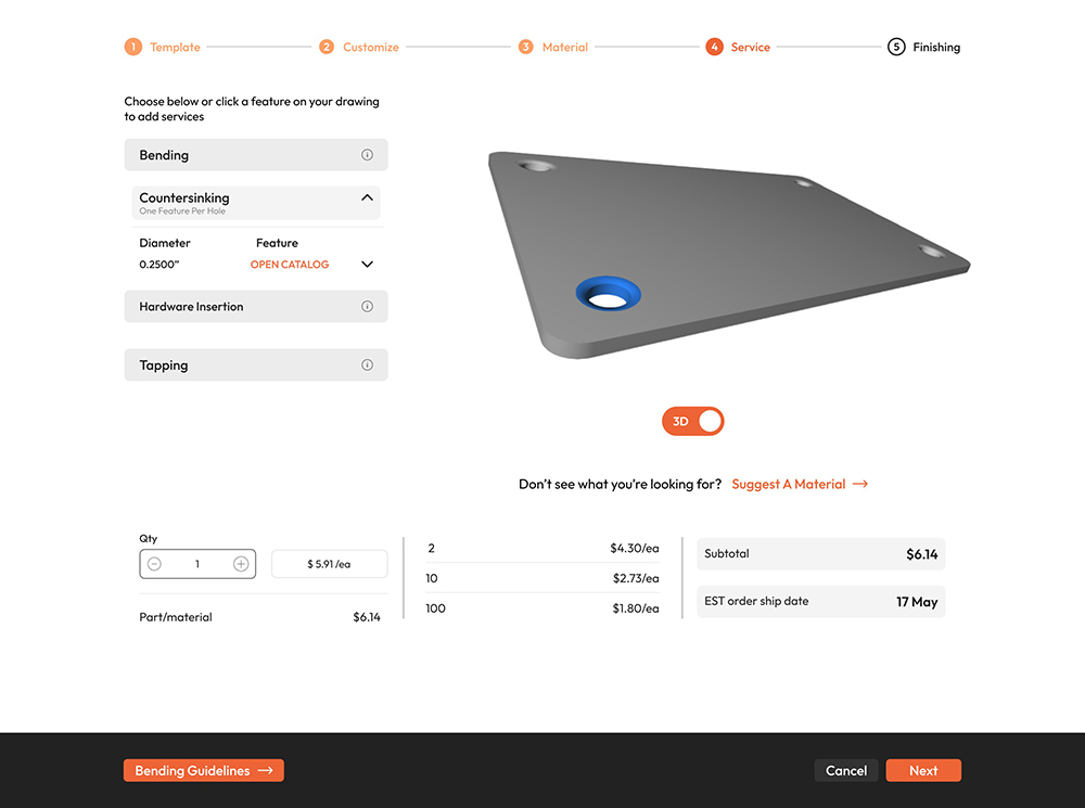
VERIFYING COUNTERSINK PLACEMENT IN OUR APP
When you upload your file to our app, you can view your part in a 3D model to ensure the final product functions as intended.
Use this model to verify that your countersinks are correctly oriented on your part. Countersinks can be placed on the
top or bottom face, so it’s important to confirm they are indicated on the correct face.
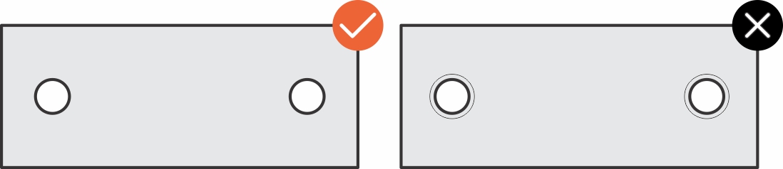
INDICATING COUNTERSUNK HOLES
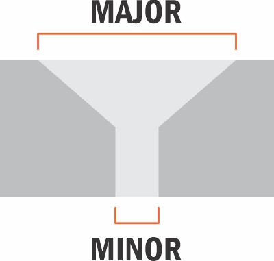
When setting up your file for countersinking, remember to include only the inner circumference of the hole (called the Minor) that is to be countersunk. Do not include the outer circumference (the size of the countersink, called the Major) in your file, as this will be cut during the machining process and will make your hole too large for countersinking. Your file should look like the example indicated here:
HOLE SIZE
The Major hole size should match or be slightly larger than the diameter of the hardware head you're using. Ideally,
use the exact diameter of the hardware head as your reference. A good rule of thumb is to make the
countersink 50% larger than the internal hole (Minor).
When selecting your hole operations for the desired hole in your design, we will automatically resize the hole to the
required size as long as the starting hole is less than 0.500” in diameter. Please ensure that you have
adequate clearance to other features and edges of the material, as the resizing process may affect the overall design.
Refer to the chart below for examples of countersinking sizes. Please note that these examples are based on
sample hardware (linked in the chart), and hardware specifications and styles may vary by manufacturer.
Imperial/SAE Examples:
| Hardware Size | Hardware Head Diameter | Countersink Minor Diameter | Countersink Major Diameter | Countersink Depth |
|
10-32, ⅜” Hex Drive |
0.411” | 0.194” | 0.411” | 0.127” |
| ¼-20, ⅜” Hex Drive Flat Head Screws |
0.531” | 0.250” | 0.531” | 0.161” |
Metric Examples:
| Hardware Size | Hardware Head Diameter | Countersink Minor Diameter | Countersink Major Diameter | Countersink Depth |
| M5 x .8mm, 14mm Hex Drive Flat Head Screw |
10mm | 5mm | 10mm | 2.8mm |
| M8 x 1.25mm, 12mm Hex Drive Flat Head Screw | 16mm | 8mm | 16mm | 4.4mm |
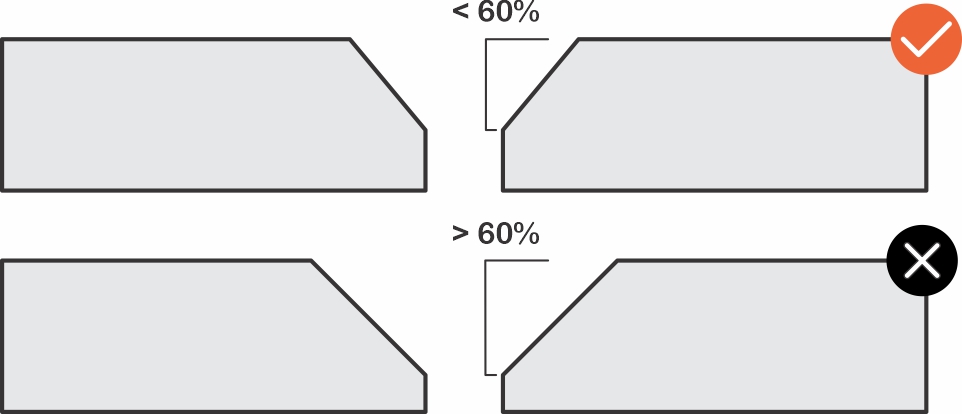
DEPTH AND ANGLE
The depth of the countersink should be no more than 60% of the material thickness to maintain structural integrity. If a deeper countersink is needed, ensure that the holes are spaced far enough apart to prevent undue stress. Depth is defined as the distance from the material surface or top of the cone to the bottom of the cone, which is typically considered the head height in flat head bolt hardware specifications.
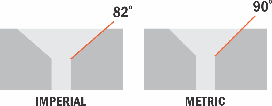
The angle of the countersink depends on the hardware being used. Ideally, the hardware should have at least 50% contact with the countersunk hole, though it doesn't need to match exactly. The standard countersink angle for metric hardware is 90°, while for imperial hardware it is 82°. We offer sizes in both angles.
SIZES AVAILABLE
The 'Major' measurement shown here refers to the larger diameter at the top of the countersink, while the 'Minor' measurement refers to the smaller diameter at the bottom of the countersink, where the hole is at its smallest
When selecting hole operations for your design, we will automatically resize the hole to the required size as long as the starting hole is less than 0.500” in diameter.
Please keep in mind that, due to resizing, you need to verify that there is adequate clearance to other features and edges of the material.
90° (Common for Metric bolts)
| Metric Flat Head Bolt | Major | Minor | Depth |
| M2 x 0.4mm | 4mm (0.157”) | 2.39mm (0.099”) | .074mm (.029″) |
| M2.5 x 0.45mm | 5mm (0.197”) | 2.49mm (0.103”) | 1.19mm (.047″) |
| M3 x 0.5mm | 6mm (0.236”) | 3.18mm (0.130”) | 1.35mm (.053″) |
| M4 x 0.7mm | 8mm (0.315”) | 4.04mm (0.164”) | 1.93mm (.076″) |
| M5 x 0.8mm | 10mm (0.394”) | 5.00mm (0.202”) | 2.44mm (.096″) |
| M6 x 1mm | 12mm (0.472”) | 6.35mm (0.255”) | 2.77mm (.109″) |
| M8 x 1.25mm | 16mm (0.630”) | 8.00mm (0.320”) | 3.94mm (.155″) |
82° (Common for Imperial/SAE bolts)
| Standard Flat Head Bolt | Major | Minor | Depth |
| 4-40 | 0.255” (6.48mm) | 0.130” (3.18mm) | .072″ (1.83mm) |
| 6-32 | 0.307” (7.80mm) | 0.164” (4.04mm) | .082″ (2.08mm) |
| 8-32 | 0.359” (9.12mm) | 0.193” (4.78mm) | .095″ (2.41mm) |
| 10-24 | 0.411” (10.44mm) | 0.199” (4.93mm) | .122″ (3.10mm) |
| 10-32 | 0.411” (10.44mm) | 0.199” (4.93mm) | .122″ (3.10mm) |
| 1/4-20 | 0.531” (13.49mm) | 0.255” (6.35mm) | .159″ (4.04mm) |
| 1/4-28 | 0.531” (13.49mm) | 0.255” (6.35mm) | .159″ (4.04mm) |
| 5/16-18 | 0.656” (16.66mm) | 0.318” (8.08mm) | .194″ (4.93mm) |
| 5/16-24 | 0.656” (16.66mm) | 0.318” (8.08mm) | .194″ (4.93mm) |
Additional details can be found from our preferred vendor, McMaster
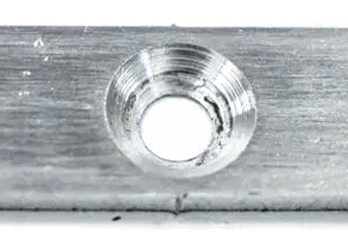
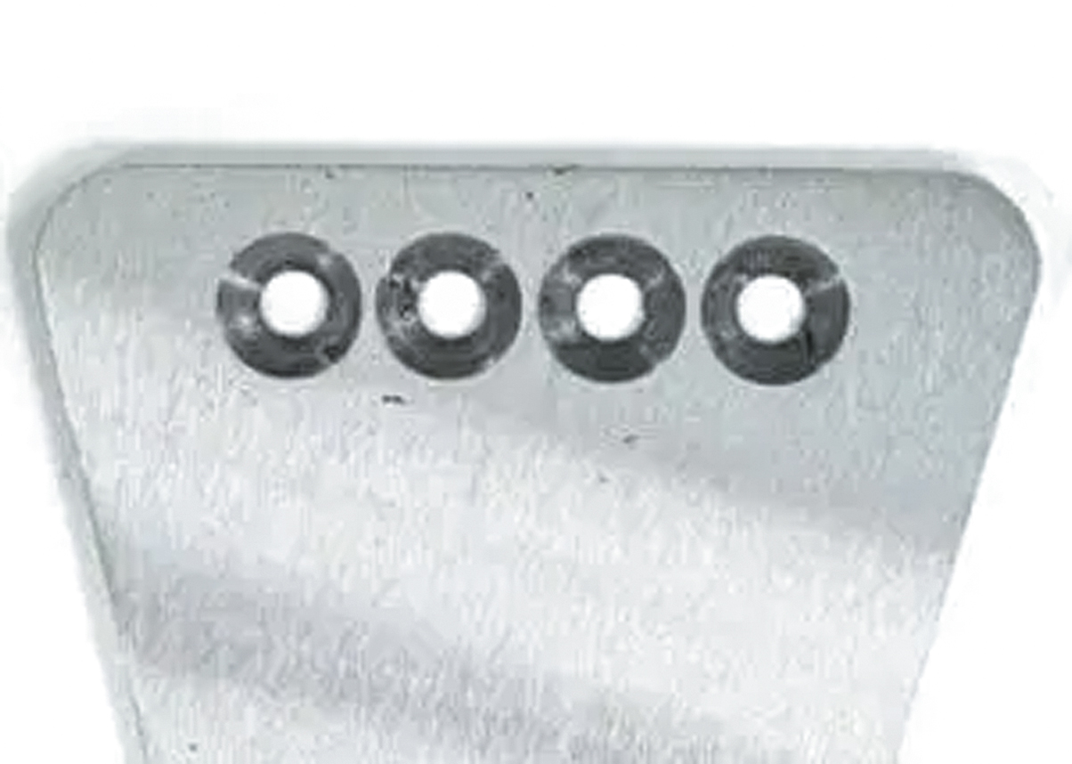
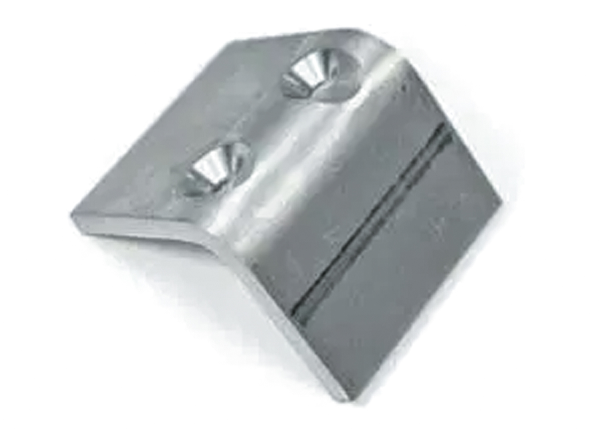
WHAT TO EXPECT FROM FINISHED PARTS
- Parts may have oil or lubricant residue on the surface
- Some light deburring may be required to remove sharp edges left by the
countersinking process - Parts may exhibit some scoring and will not have a perfectly machined finish
- Powder coating will add 0.002” to 0.005” (0.051mm to 0.13mm) per side. We’ll adjust the hole size accordingly,
but please note that the fit may be tight on countersinks with powder coating
Pre-flight Checklist
- Ensure your file is in an accepted format (2D: .dxf, .dwg, .ai, .eps; 3D: .step, .stp)
- Ensure all holes and cutouts are at least 50% of the material thickness for laser cut parts
- Ensure all holes and cutouts are at least 0.070” for most waterjet cut parts
- For all CNC routed parts, holes and cutouts must be at least 0.125”
- Create your file at a 1:1 scale, preferably using inch or millimeter units
- Ensure all objects are placed on the same layer
- Remove all stray points, duplicate lines, empty objects, and text areas
- Ensure no shapes have open contours
- Ensure all shapes are united, combined, or merged
- Convert all text to outlines or paths
- Ensure cut-out text (reversed text) includes bridges or is stencilized
Materials Available for Countersinking
Currently, we offer countersinking for the following 7 materials:

Validate your login