


Back to Top
SETUP AND COST
Bending your metal and plastic parts adds a $19.00 minimum fee to your cart total
Save up to 70% or more with quantity discounts! These discounts are calculated based on factors such as material, operation type, number of operations per part, and quantity of duplicate parts. Our app automatically applies quantity discounts to your order
Visit our processing page for information on typical lead times for parts with bending and other services. We offer free 3-5 day shipping for standard orders (larger quantities may require additional time). Most bent parts will ship via ground, as they will exceed 2″ in height when packed
MATERIAL LIMITS
- 0.030” – 0.250” thickness
- Minimum flat part size
- Minimum shortest side .375”
- Minimum longest side 1.5″ – 2.5″ depending on material thickness
- Maximum flat part size
- 44″ x 30″ in all materials
- Maximum bend length 16″ – 44″ depending on material thickness
- No 6061/7075 Aluminum
- No Grade 5 Titanium
- No AR400/AR500
- No 1075 Spring Steel
SERVICE AND MATERIAL LIMITATIONS
Before planning your next project, it's important to understand the limitations of
metal and plastic bending
General
• Maximum flat part size 44″ x 30″
• Maximum bend length 16″ – 44″ depending on material thickness
• Maximum thickness of .250”, depending on flange length
Metal
• Maximum bend angle will be limited to 90° for specific materials
• Metal parts will have a +/- 1-2° angle tolerance depending on bend length
Polycarbonate
- Polycarbonate parts will have a +/- 5-degree bend angle tolerance on
bends up to 24″ long - Polycarbonate parts will have a +/- 7-degree bend angle tolerance on bends
longer than 24″ - Polycarbonate parts are limited to up to 3 bends or flanges per part. More than 3 bends will require a custom quote.
- Polycarbonate bends can be no greater than 90° and no less 45°
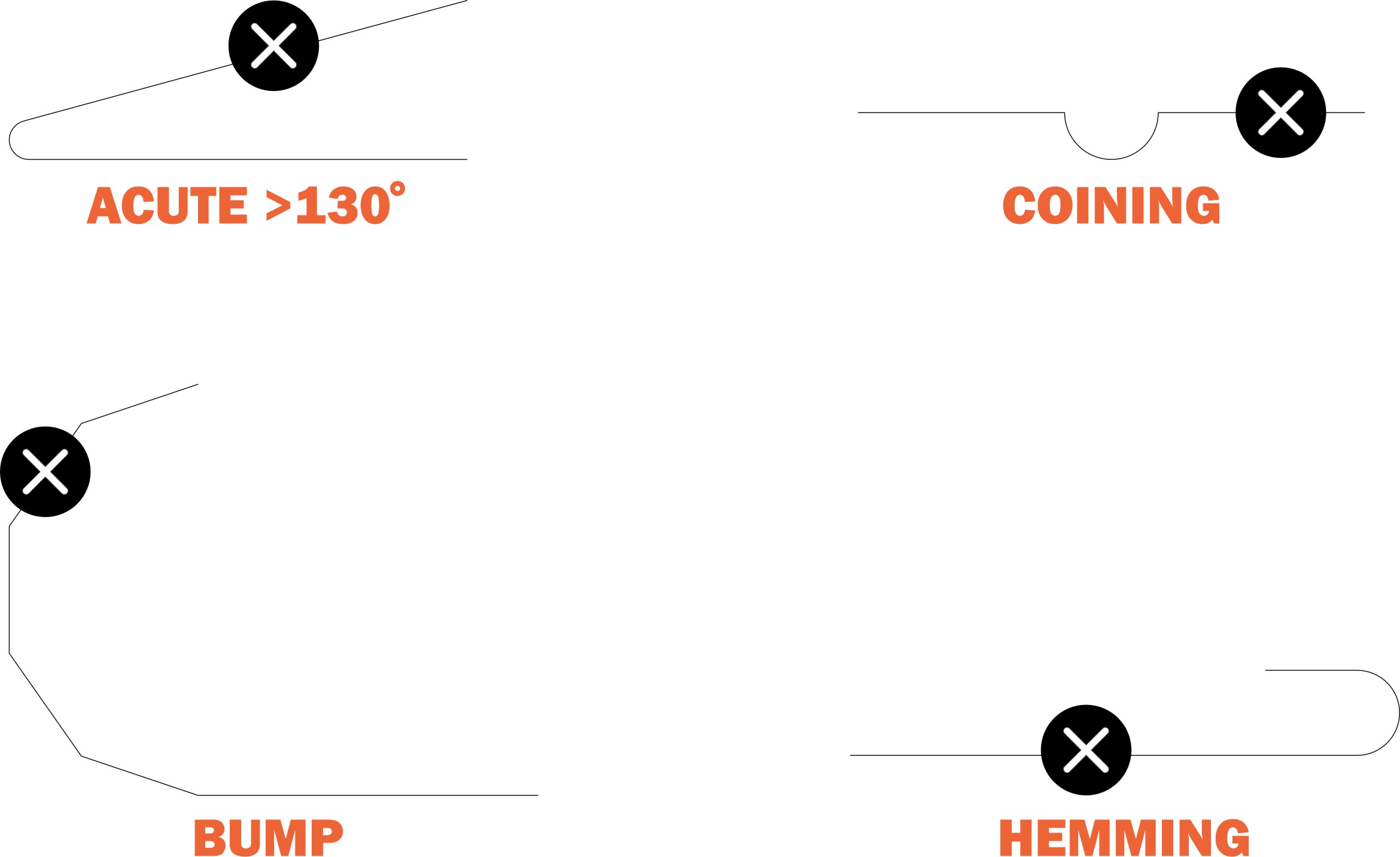
While we’re happy to bend your parts as needed, there are some types of bends we don’t offer
- No acute angles greater than 130°
- No obtuse angles less than 5°
- No curl, bump, or roll forming
- No coining
- No hemming
- For polycarbonate parts,
no joggle bends
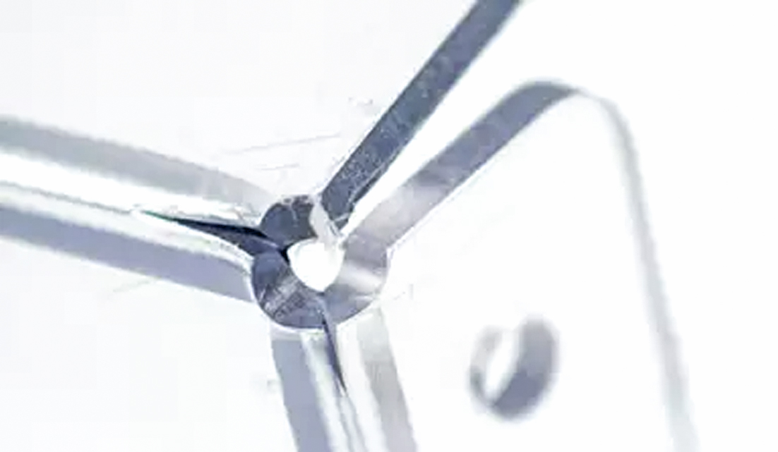
OUR PROCESS: AIR BENDING
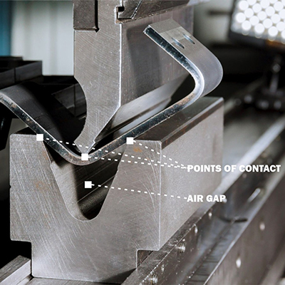
At CraftCutCreate, we form sheet metal and plastic using air bending. During this process, there are only three points of contact between the material and the tooling: the punch and the two sides of the die. An air gap in the die’s trough under the flange's apex gives this process its name
EFFECT ON BEND RADIUS
With air bending, the effective radius is influenced by the tooling combination (die + punch) as well as the material’s thickness and strength. Depending on your material choice, the effective radius (the internal radius after bending) may be smaller for thicker gauges, or vice versa. You can find our effective bend radii listed under Material Details on each material page
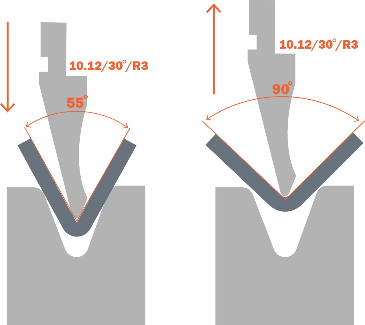
POLYCARBONATE LIMITATIONS
To bend polycarbonate, flanges must be overbent to achieve the desired angle due to the material's spring back. As a result, some designs that are feasible in sheet metal may not be possible in plastic
In this example, the material is bent to 120-130 degrees to achieve a 90-degree angle
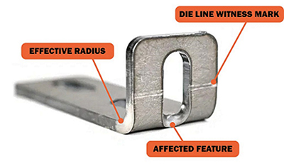
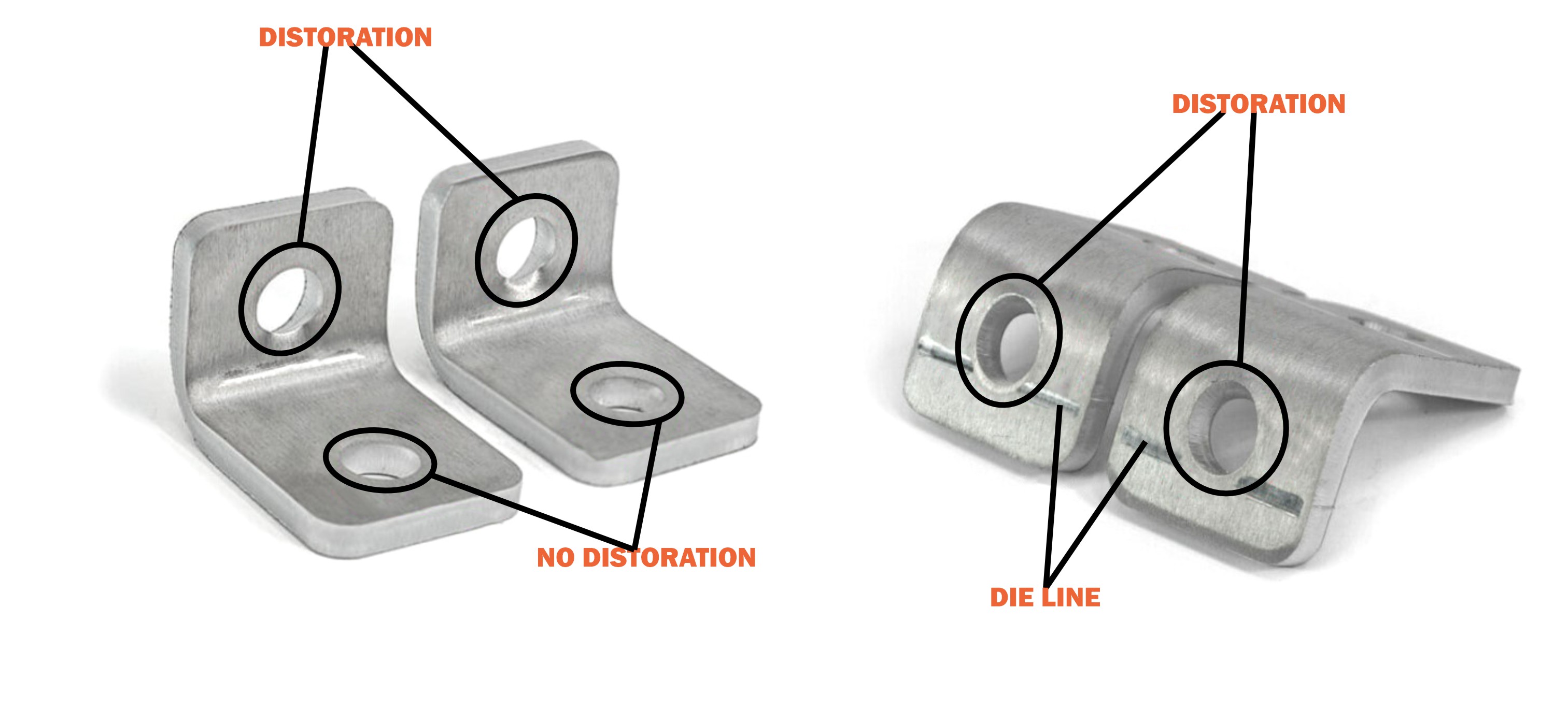
DIE LINE CONSIDERATIONS
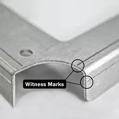
Die lines extend across the full width of the tooling (die) used to form parts. When a part is bent, witness marks, known as die lines, are left where the die contacts the part
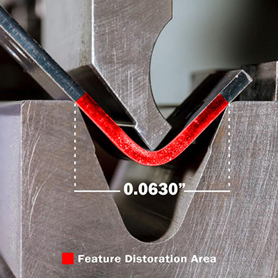
THE PROBLEM: FEATURE DISTORTION
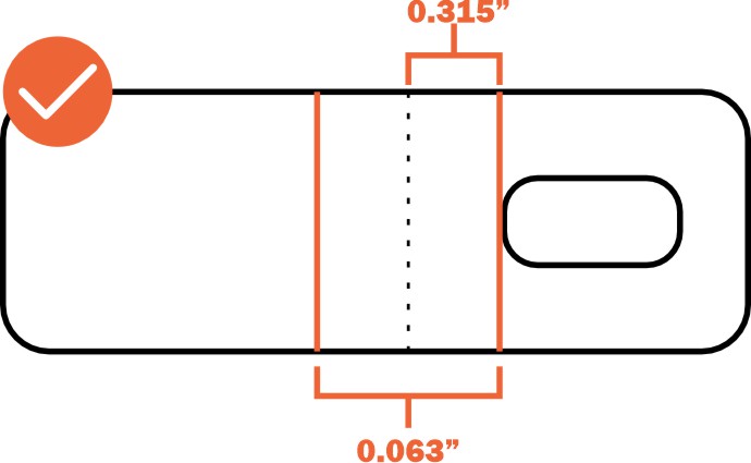
While the effective bend radius for our materials ranges from 0.024″ to 0.250″, the dies we use will span at least 0.472″ to 1.575″ across the bend line. We cannot offer cosmetic protection along the die lines, so holes, edges, and other cutouts may experience distortion during the bending process
For example, a part cut from 0.104” mild steel will be bent with a 0.630” die. Therefore, any cut feature that is 0.315” or less from the bend line (center of the bend) will be distorted during the forming process
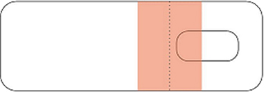
When ordering your part from us, we will highlight the feature
distortion caution area as you configure your bend angles.
In the screenshot, the hole in the yellow area will be distorted
You can measure the die width on your flat pattern before uploading your file. Refer to the die width for your material in our material library. The center of the die width will align with the bend line, as shown in this example
.104″ Mild Steel
Die width: .630″
Solution
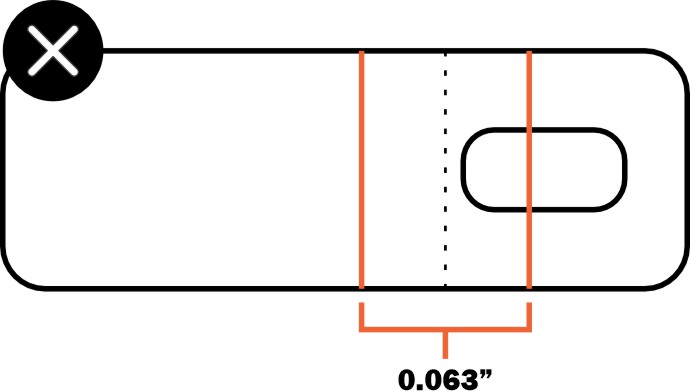
If features fall within the die line of our tooling, you should remove or adjust their location. Refer to each material page to see the die we will use for your chosen material and ensure your cut features are at least half the die’s width away from the bend line
Ensure all holes and cutouts in your design are outside the die width area. In the example below, the holes on one side of the bend fall within the distortion area, while those on the other side do not
Refer to our Bending Deformation Guidelines for more information
File Setup
Before sending us your first file for bending, here are the basics you need to know. If you have any questions,
feel free to contact our support team
Accepted File Formats for Our Instant Quote System

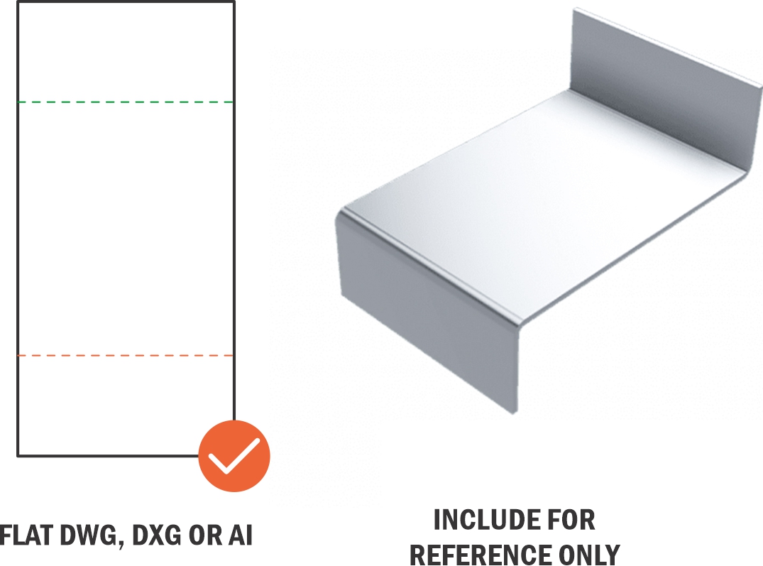
Ensure the part design you upload for bending is either a 2D vector file (.dxf, .dwg, .ai, or .eps format) or a 3D .step or .stp file.
You will be able to view your bends in a 3D model during the checkout process to verify the angles and flange orientations are correct
| SOFTWARE | FORMAT | BEND LINE |
Fusion360 |
.dxf, .step, .stp | Solid line (default) |
| Fusion360 | .ai | Solid, separate color from cut lines |
| SolidWorks | .dxf, .step, .stp | Dashed line (not hidden) |
| AutoCAD | .dxf, .step, .stp | Dashed line (not hidden) |
| CorelDraw | .eps | Solid, separate color from cut lines |
| Inkscape | .eps | Solid, separate color from cut lines |
Please upload your part design as either a 2D vector file (.dxf, .dwg, .ai, or .eps format) or a 3D file (.step or .stp format).
If you design your parts using non-CAD software like Adobe Illustrator, please send us the original .ai file. We’ll handle the conversion. While we accept .ai and .eps files, it's crucial that your bend lines are parallel when uploaded from these programs to avoid processing delays
To ensure the fastest turnaround on your order, we recommend using CAD software to design your parts
To learn more about designing for laser cut sheet metal, refer to our Laser Cutting Guidelines
For design guidelines on CNC routed polycarbonate, please refer to our CNC Machining Guidelines
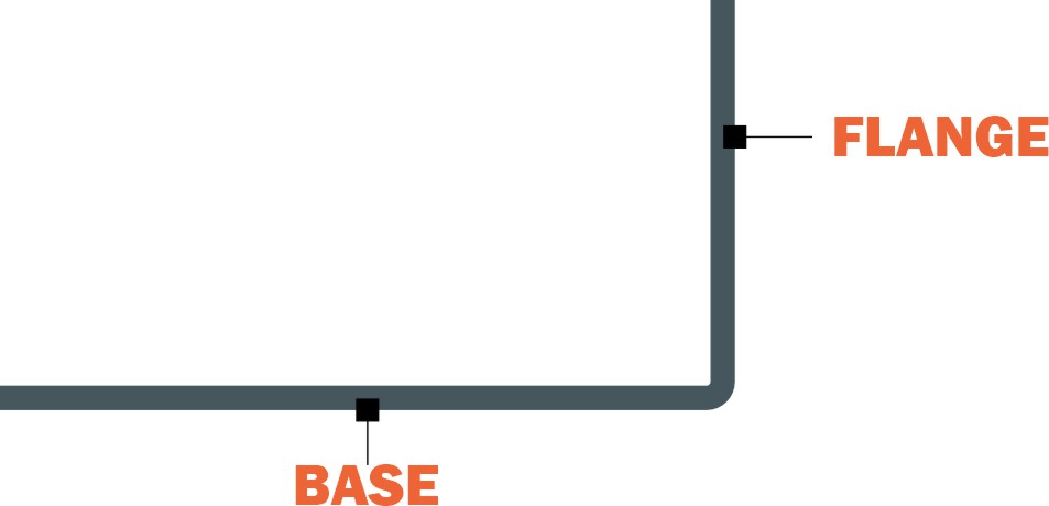
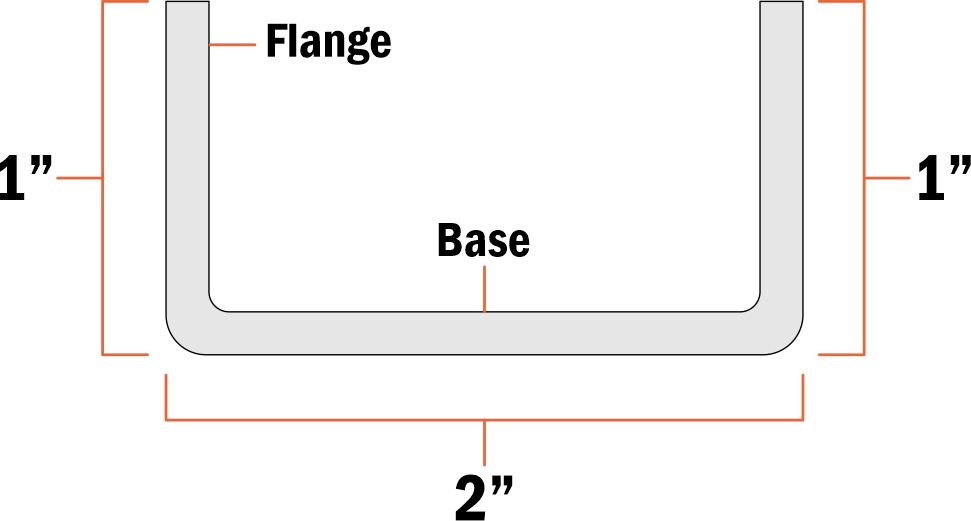
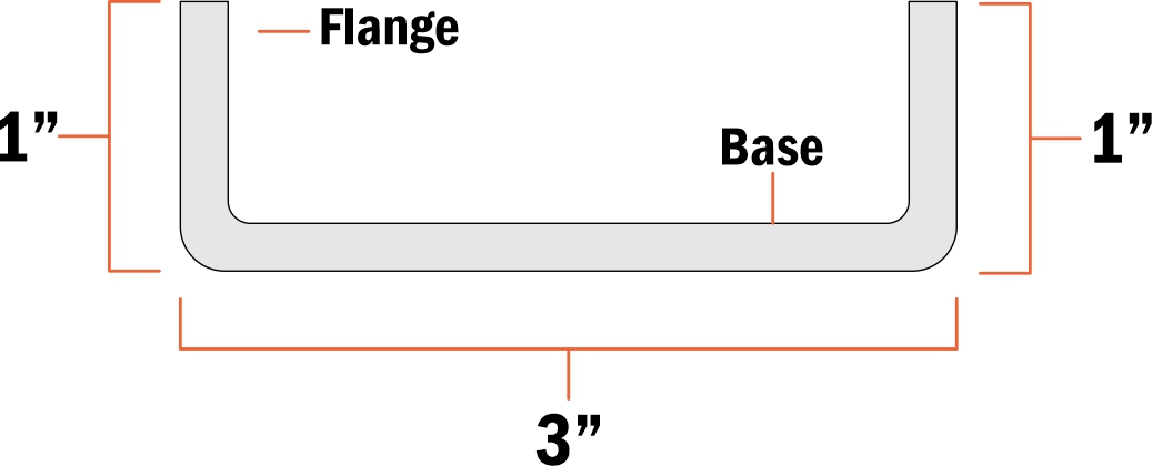
FLANGE AND BASE
Before we start, it's important to know some basic terms:
the base and the flange.
The flange is the edge that you will be bending
| Design Considerations | |
| Min Bend Part Size | .375" x 1.5" |
| Max Bending Flat Part Size | 44" x 30" |
| Min Flange Length (Before Bend/Flat Pattern) 90° or less (obtuse) | .255" |
| Min Flange Length (After Bend) 90° or less (obtuse) | .286" |
| Max Bend Length | 44" |
| Die Width | .472" |
| Effective Bend Radius @ 90° | .024" |
| Max Bend Angle | 130° |
MINIMUM AND MAXIMUM FLANGE LENGTH
The minimum flange length varies depending on the material and thickness you use. Refer to our materials directory and check the Material Details for the correct dimensions for your chosen material
This example shows the bending information for 0.040″ 5052 Aluminum
The maximum flange length for 4-sided box bends is 3.50″ for all materials if no hardware is installed. With hardware, the maximum flange length is 3.00″. More information is available here
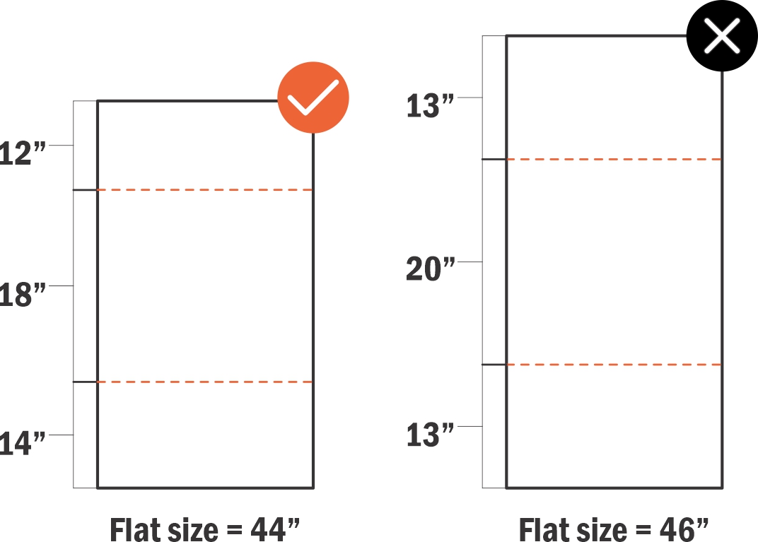
MAXIMUM FLAT SIZE
The maximum flat part size is 44″ x 30″. This size includes the total of your base and flanges
BEND LINES IN 2D FILES
"If you upload a 2D vector file, we will use the flat .dxf (or .ai file if you use Adobe Illustrator) for cutting and bending.
Please indicate your bend locations in the drawing using a line, with the bend lines marking the center of each bend.
During the ordering process, you can specify bend angles for each line. If a bend line is missing or insufficient,
you will receive an error message in the app."
- Feel free to use any color for your lines; our system ignores line colors.
- When using Adobe Illustrator, avoid dashed lines and ensure your lines are parallel to one flat edge.
- Refer to our bending export guides for help with exporting cut-ready files.
- For 3D file setup tips, please refer to our STEP/STP file guide.
BEND DEDUCTION
Bend deduction compensates for material stretch caused by forming. It varies with each material type, thickness,
and bend angle. Use our calculator to ensure your measurements are accurate
Note for advanced users: Ensure all calculations are for air bending, not coining.
BENDING CALCULATOR
After obtaining your new measurements from the bend calculator, adjust your file accordingly.
Reduce the length of your base and flange to account for the bend length, also known as the bend deduction.
The illustration below shows an example, with the green line indicating where the bends will occur.
MEASURING THE LENGTHS OF
FORMED FLANGES
Always measure formed flange lengths from the
apex of the bend
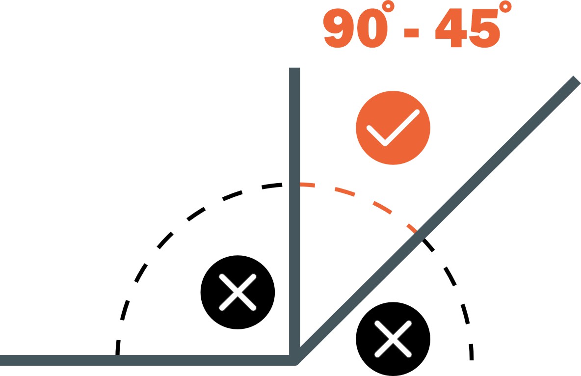
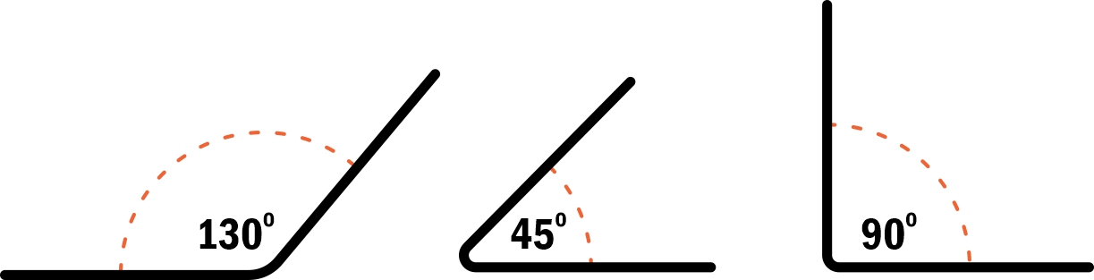
ACUTE AND OBTUSE BENDS
The bend angle is measured from the outside of the bend. In the illustration below, the acute bend is shown as 130°.
Each material stock thickness has minimum and maximum angle limits. You can check these limits on the material pages
Note: The bend radius for your part can be found on the material page or in the bending calculator.
Custom bend radius are not available
C-CHANNEL OR U-CHANNEL BENDS
SHEET METAL PARTS
For these bends in sheet metal, the base must be at least twice as wide as the flange length. For example, a 1” flange on two sides requires a minimum 2” base (the remaining material or the “bottom of the U”). The base can be greater than the 2:1 ratio; for instance, a 5” base with 1” flanges is acceptable (a 5:1 ratio)
POLYCARBONATE PARTS
For these bends in sheet metal, the base must be at least twice as wide as the flange length. For example, a 1” flange on two sides requires a minimum 2” base (the remaining material or the “bottom of the U”). The base can be greater than the 2:1 ratio; for instance, a 5” base with 1” flanges is acceptable (a 5:1 ratio)
WINDOW OR JOGGLE BENDS
SHEET METAL PARTS
Window bends and joggle bends are permitted up to 90° for sheet metal parts.
More acute angles require review by our team. Refer to the charts for your chosen material to
find the minimum and maximum joggle flange values
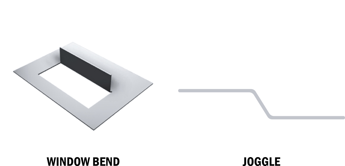
POLYCARBONATE PARTS
Joggle bends are not available for polycarbonate parts, but we can provide window bends up to 90°.
Parallel bends in opposite directions can be made in polycarbonate as long as the flanges are at least 3″ apart
when measuring from the center or apex of each bend, and one of the flanges is no longer than 5″
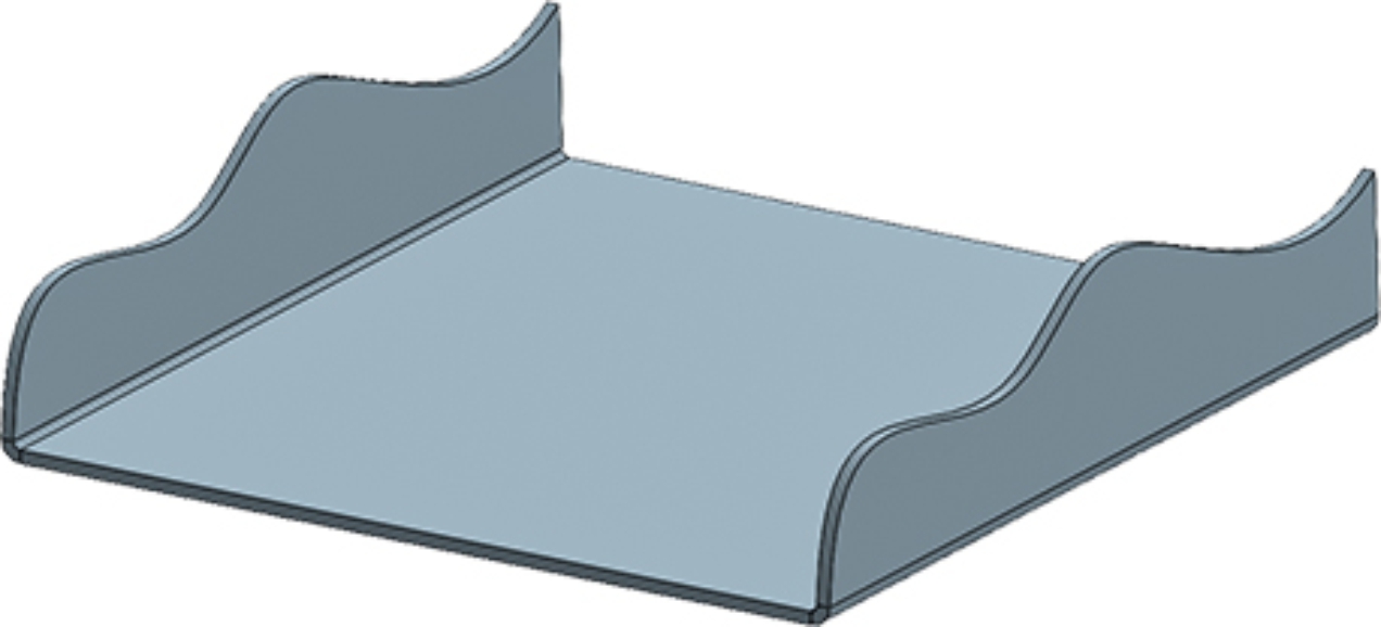
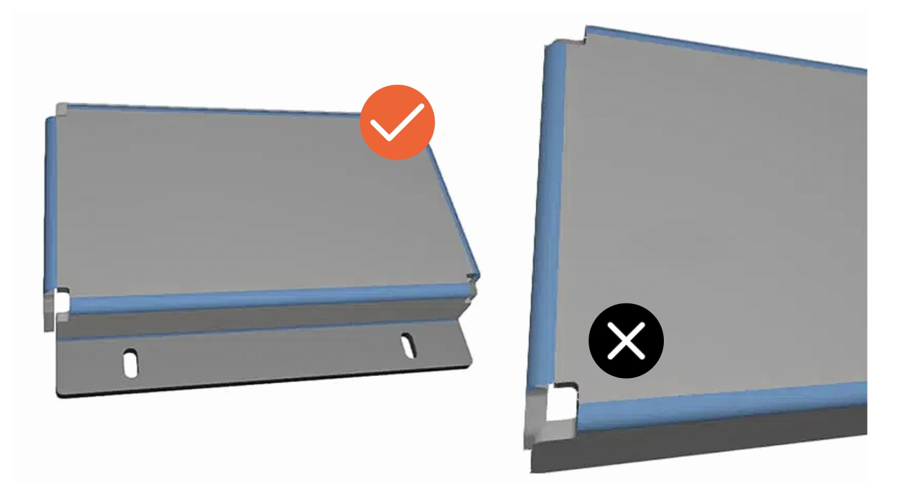
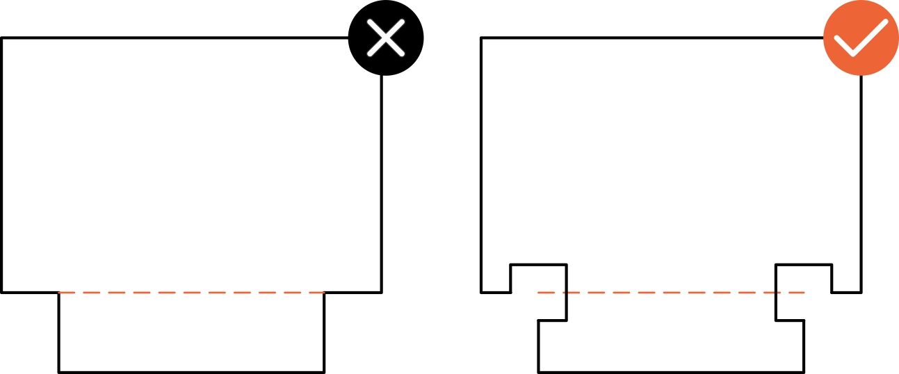
ODD FLANGE SHAPE
We allow irregular flange shapes, but a flat piece is needed for bending.
To achieve this, add tabs to create a flat surface parallel to the bend.
Refer to the example below for proper breakoff tab usage.
|
|
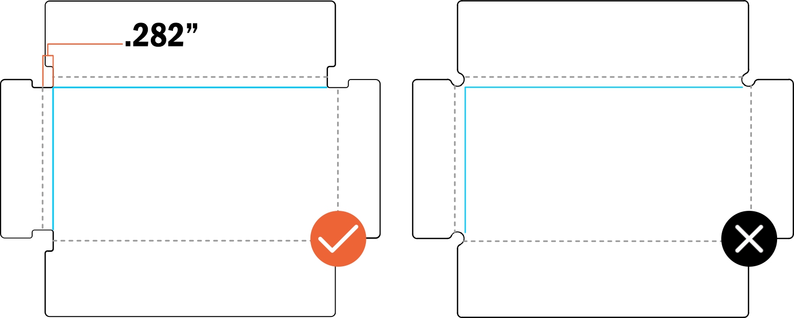
BREAKOFF TAB LENGTH
- Your breakoff tab must be sufficiently long relative to your part’s overall flat length.
Please note that we may request a longer tab if necessary for a successful bend,
depending on your design’s geometry.
-
- 0-5 inch part: 0.500″ minimum breakoff tab
- 5-10 inch part: 1.000″ minimum breakoff tab
- 10+ inches: 1.500″ minimum breakoff tab
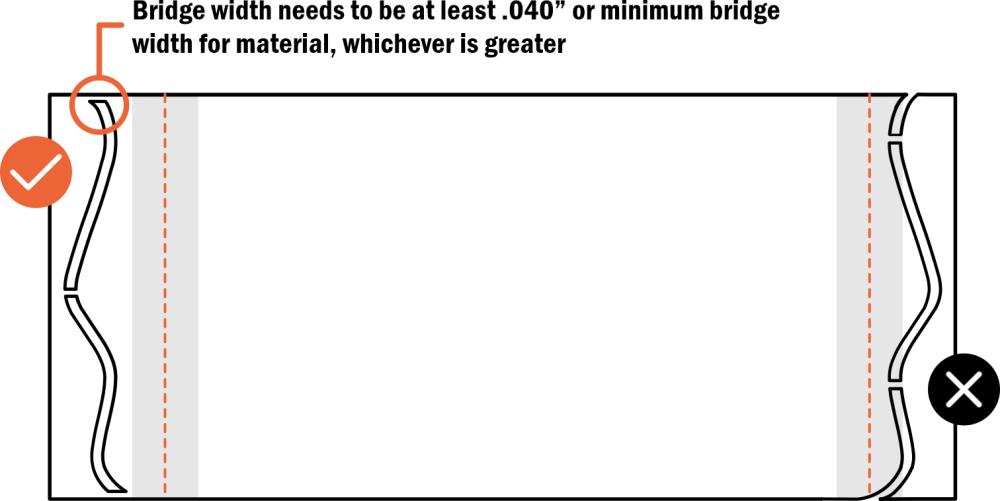
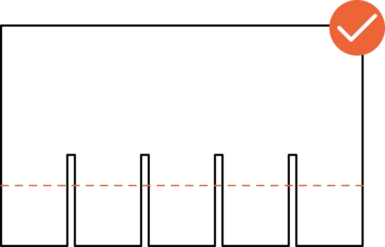
CONNECTING BRIDGES
- Ensure there are at least 2 connecting bridges from your part to the breakoff tab
- Additional bridges are beneficial for longer flanges. We recommend the following:
- 0-10 inch flange: At least 2 connecting bridges
- For every extra 10 inches of flange length, add at least one more bridge
- Ensure the connecting bridges are at least 0.040” wide or meet the minimum bridge width for the material, whichever is larger.
Bridges that are too thin may break during the bending process. - Remember that you'll need to remove the breakoff tabs when your parts arrive, so choose an appropriate bridge width.
- For materials 0.080” or thicker, it's advisable to keep bridge widths at no more than 50% of the material thickness
KEEP OUTSIDE OF DIE LINES
- The breakoff tabs' connecting bridges must not fall within the die lines. Tabs are
vulnerable to breakage if the connecting bridges are placed within the die area.
ADD TO EXTERIOR OF PART
We need break-off tabs added to the exterior of parts, as we cannot use
tabs placed on the interior of a part.
WATCH VIDEO ON IRREGULAR FLANGES
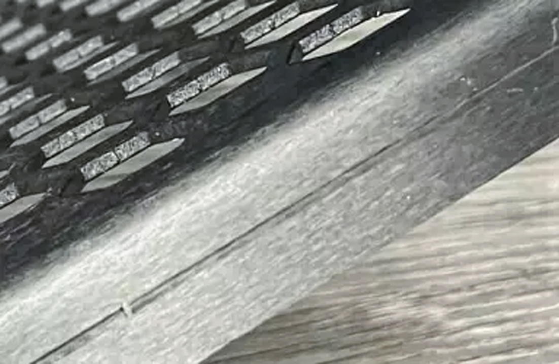
BEND RELIEF NOTCHES
To reduce corner bulging and prevent tearing in your bent parts, incorporate bend relief notches into your design.
These notches, which are narrow cuts or circles at the corners, should be at least 50% of the material’s thickness in width.
The depth should be equal to the bend radius + the material thickness +0.020”
These notches reduce stress on the inner radii of the flanges and prevent the corners of the bends from interfering with the
base material. For more details, refer to our guide on designing bend reliefs and our
Bending Deformation Guidelines.
POLYCARBONATE CONSIDERATIONS
Polycarbonate parts require the minimum necessary bend relief to avoid cracking during bending.
Refer to our guide to find the required bend relief depth for each polycarbonate sheet thickness.
Since polycarbonate parts are overbent to achieve the desired angle, ensure adjacent flanges bent in the
same direction have sufficient clearance to avoid collision.
Additionally, polycarbonate parts require rectangular bend reliefs. Any transition in a
corner will add stress and may result in tearing
WHAT TO EXPECT
GENERAL
- Simple, single-bend parts will have a tolerance of +/- 0.015” from bend to edge
- Multi-bend parts will have a tolerance of +/- 0.030” from bend to edge, with each additional bend adding at least 0.015” to the tolerance
- Witness marks from the bending process will be visible. Depending on the material, these marks can become deeper and more noticeable
- Currently, we do not offer special protection for cosmetic parts
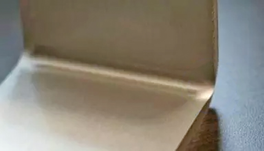
- Some bulging at the ends of the bend is to be expected
SHEET METAL
-
Sheet metal parts will maintain a +/- 1-degree bend angle tolerance
for bends up to 24″ in length -
Sheet metal parts will maintain a +/- 2-degree bend angle tolerance
for bends longer than 24″
POLYCARBONATE
-
Polycarbonate parts will maintain a +/- 5-degree bend angle tolerance for bends
up to 24″ in length -
Polycarbonate parts will maintain a +/- 7-degree bend angle tolerance for bends
longer than 24″ -
Polycarbonate parts may develop minor surface edge cracks, depending on the
material thickness and bend angle -
Polycarbonate parts will exhibit noticeable cracking in stressed areas if adequate relief
is not provided for each bend -
Polycarbonate parts are limited to a maximum of 3 bends or flanges per part.
Parts with more than 3 bends will require a custom quote -
Polycarbonate bends must be between 45° and 90°
COMMON ISSUES
COMBINED LINES
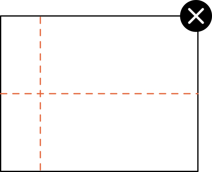
Bends on a common axis must be joined, as shown in the example.
If not joined, each bend will be treated individually
INTERSECTING BENDS
We cannot bend intersecting lines without separate flanges.
Please refer to our bending design guidelines for more information
INSUFFICIENT OR MISSING BEND RELIEF
Certain designs require bend relief to avoid damage to the part. Without proper relief, a part cannot be bent accurately.
This is especially critical for polycarbonate parts, as the material is prone to cracking. For more information,
check out our guide to designing bend reliefs and our Bending Deformation Guidelines
YOU’RE READY TO BEND
Although metal and plastic forming is a deeply complex process,
we at Craft Cut Create strive to make part bending as easy as possible.
Have questions? Reach out to our support team
Happy bending!
Pre-flight Checklist
- Ensure your file is in an accepted format (2D: .dxf, .dwg, .ai, .eps; 3D: .step, .stp)
- Ensure all holes and cutouts are at least 50% of the material thickness for laser cut parts
- Ensure all holes and cutouts are at least 0.070” for most waterjet cut parts
- For all CNC routed parts, holes and cutouts must be at least 0.125”
- Create your file at a 1:1 scale, preferably using inch or millimeter units
- Ensure all objects are placed on the same layer
- Remove all stray points, duplicate lines, empty objects, and text areas
- Ensure no shapes have open contours
- Ensure all shapes are united, combined, or merged
- Convert all text to outlines or paths
- Ensure cut-out text (reversed text) includes bridges or is stencilized
Materials Available for Bending

Validate your login