Back to Top
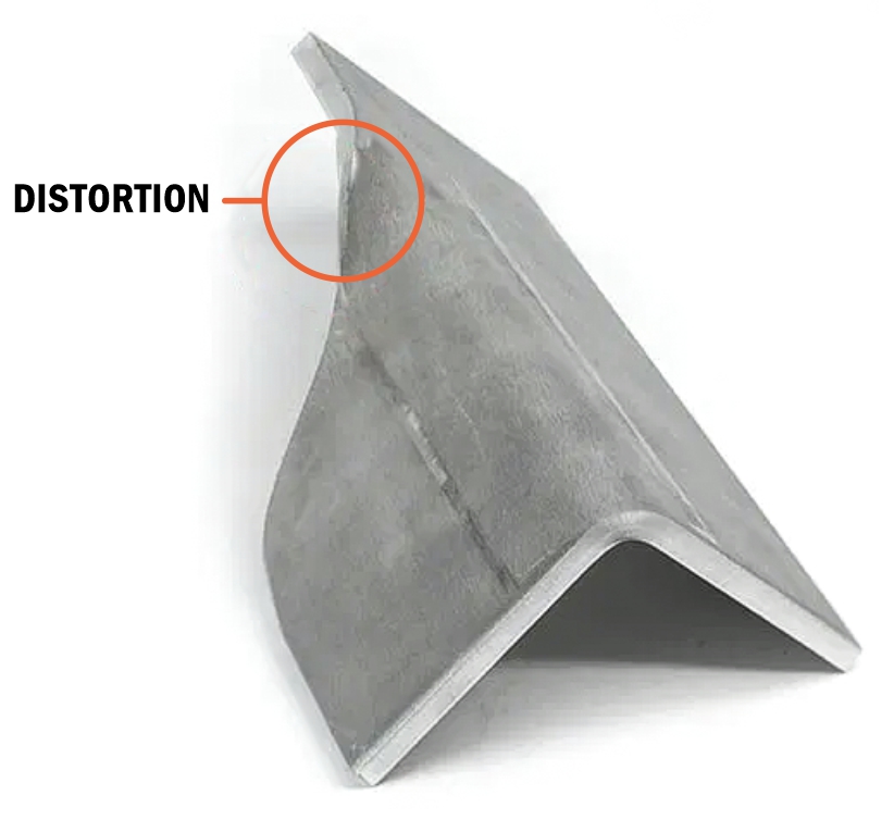
TAPERED FLANGES
Every material we bend has a minimum flange length for bending. When flanges taper below this minimum, there isn't enough contact on the tooling to apply force effectively and form the tapered area, leading to flange distortion.
Additionally, in thicker and stronger materials like stainless steel and Chromoly, an asymmetrical flange can cause the part to "pull" during the bending operation. Since the bend is unevenly supported, this can result in parts that are out of tolerance and pose a safety hazard for press brake operators.
Solution
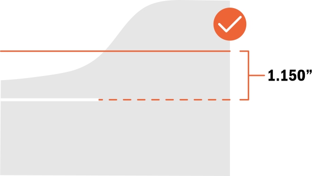
To prevent distortion, add a relief along the bend line until the
minimum flat flange length is reached.
For more details, please refer to our Guide to Designing Bend Reliefs.
For more information, refer to Our Process: Air Bending. The minimum flat flange length and minimum overall dimension for formed flanges are listed on each material's info page.
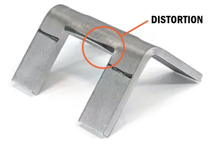
UNSUPPORTED BEND
If a flange does not meet the minimum flat flange requirement across the length of the bend, we will be unable to form the flange within our established tolerances. Bending the part as designed would result in significant deformation, as shown here.
Solution (.187″ thickness or less)
To prevent distortion in areas that cannot bend, you can add reliefs as shown in the example below.
For more information, refer to our Guide to Designing Bend Reliefs.
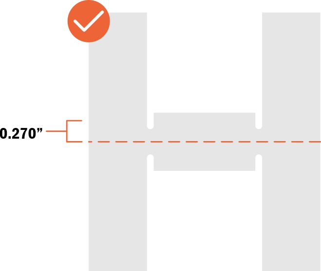
0.187” 5052 Aluminum
Effective Bend Radius (after bend): 0.250”
Recommended Bend Relief Depth if measured from bend line:
Effective Bend Radius + 0.020”
Bend Relief Depth: 0.270”
Solution (.250″ thickness)
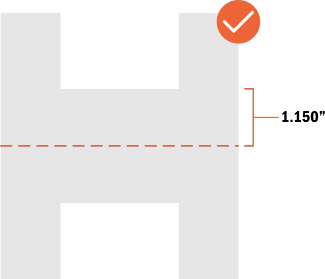
To form the material successfully, approximately 50% of a bend’s length must meet the minimum flat flange length. If you receive an unsupported bend error for thicknesses greater than 0.187″, please increase the flange length across the bend.
0.250” 5052 Aluminum
Minimum Flat Flange Length (before bending): 1.150″
For safety and tolerance reasons, materials 0.187″ and thicker may need to meet the minimum flange length on both sides of the
bend line for the entire bend length
The minimum flat flange length (before bending) and minimum overall dimension (formed flange length) can be found on
each material's info page.
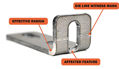
DIE LINE CONSIDERATIONS
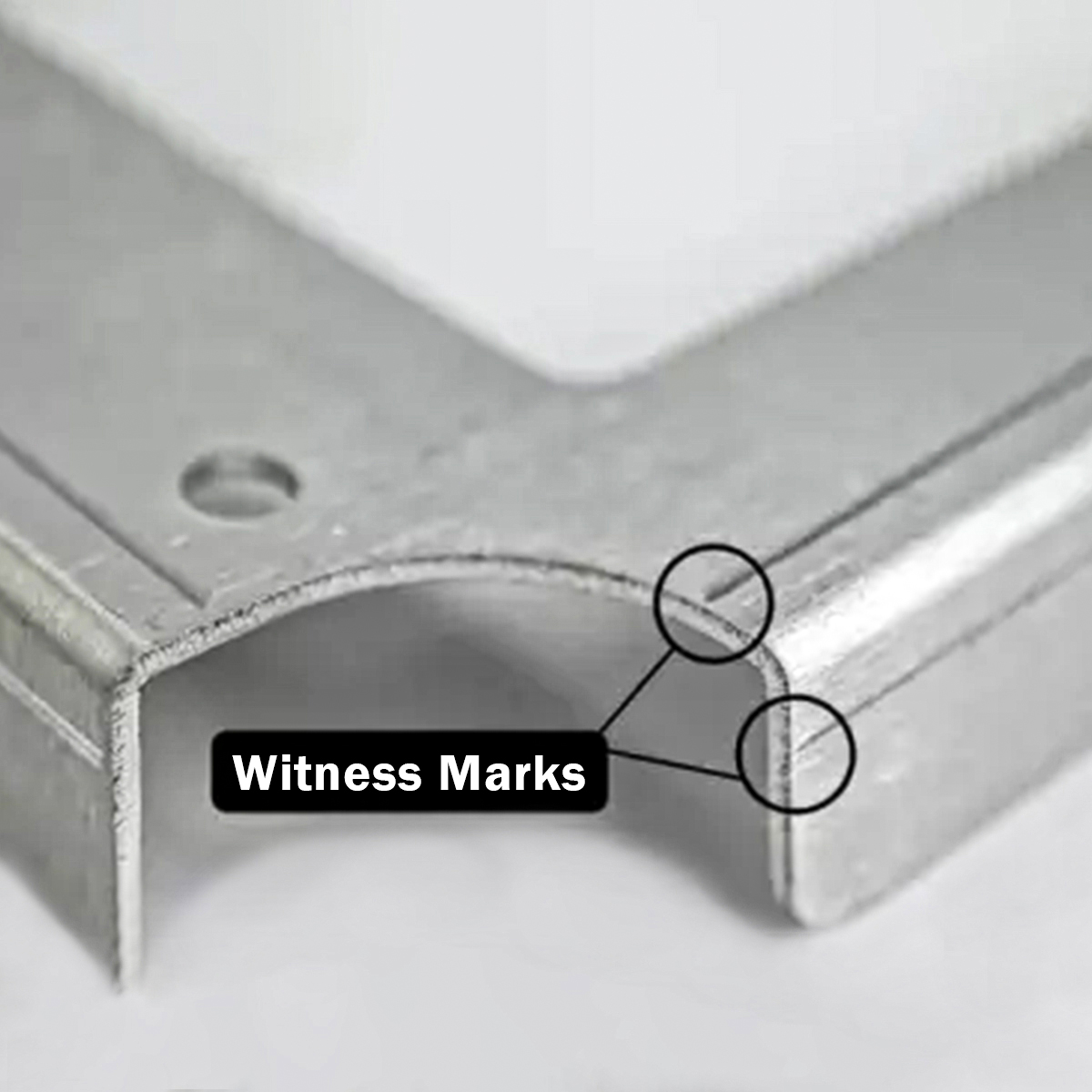
What is a die line?
Die lines represent the full width of the tooling, or die, used to form parts. When a part is bent, witness marks are left where the die contacts the part. These contact points are what we refer to as die lines.
The problem: feature distortion
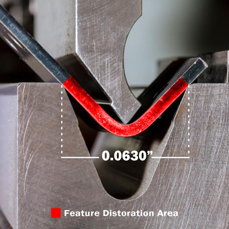
While the effective bend radius for our materials ranges from 0.024″ to 0.250″, the dies we use will span at least 0.472″ to 1.575″ across the bend line. We cannot offer cosmetic protection along the die lines, so holes, edges, and other cutouts may become distorted during the bending process.
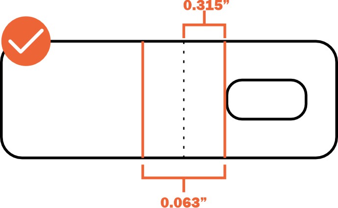
For example, a part cut from 0.104” mild steel will be bent with a 0.630” die. This means that any cut feature 0.315” or less from the bend line (center of the bend) will be distorted during the forming process.
Large cutouts and other features in the die line can cause uneven pressure during the bending process, potentially resulting in the bend line shifting and not being square.
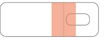
When ordering your part from us, we will highlight the feature distortion caution area when you configure your bend angles. For example, the hole in the orange portion of this screenshot will be distorted.
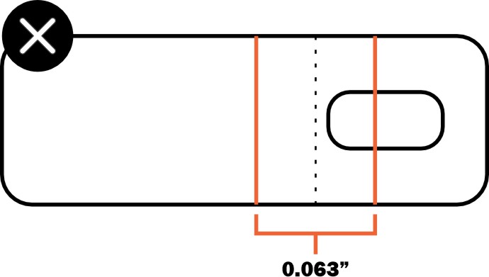
You can measure the die width on your flat pattern before uploading your file. Reference the die width for your material from our material library. The center of the die width will align with the bend line, as shown in this example.
.104″ Mild Steel
Die width: .630″
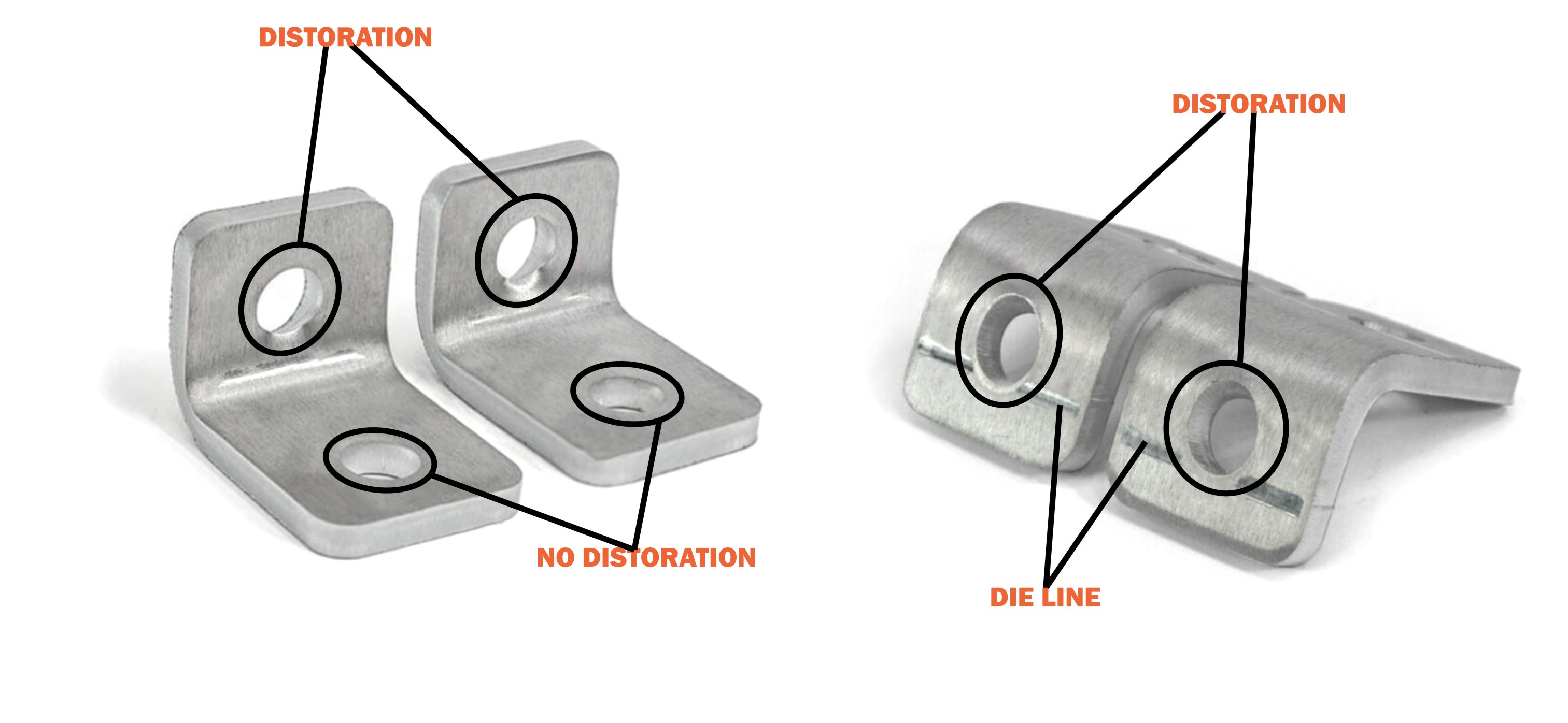
Solution
If features fall within the die line of our tooling, you should remove them or adjust their location. Refer to each material page to see the die we will use for your chosen material, and ensure your cut features are at least half the die’s width away from the bend line.
Ensure all holes and cutouts in your design fall outside the die width area. In the examples below, the holes on one side of the bend are within the distortion area, while those on the other side are not.

Validate your login