


Back to Top
Accepted File Formats for Our Instant Quote System:


| Adobe Illustrator | .ai |
| AutoCad | .dxf, .step, .stp |
| CorelDraw | .eps |
| Fusion360 | .dxf, .step, .stp |
| Inkscape | .eps |
| SolidWorks | .dxf, .step, .stp |
We accept 2D vector files for laser cutting in the following formats: DXF (preferred), AI (Adobe Illustrator), EPS, and DWG.
We also accept 3D files in STEP and STP formats. If you encounter any issues uploading your file, please refer to our STEP/STP file guide.
If you design your parts using non-CAD software like Adobe Illustrator, Inkscape, or CorelDraw, please send us the original .ai or .eps file. We'll handle the conversion on our end.
Please note that we cannot accept or process STL (mesh) files or raster files such as JPEG, TIFF, PNG, or BMP.
Only have a raster file (JPEG, GIF, PNG)?
We offer tutorials to help you convert your artwork to a vector format using Adobe Illustrator and Inkscape.
TOOLING DIAMETER AND RADIUS SPECIFICATIONS
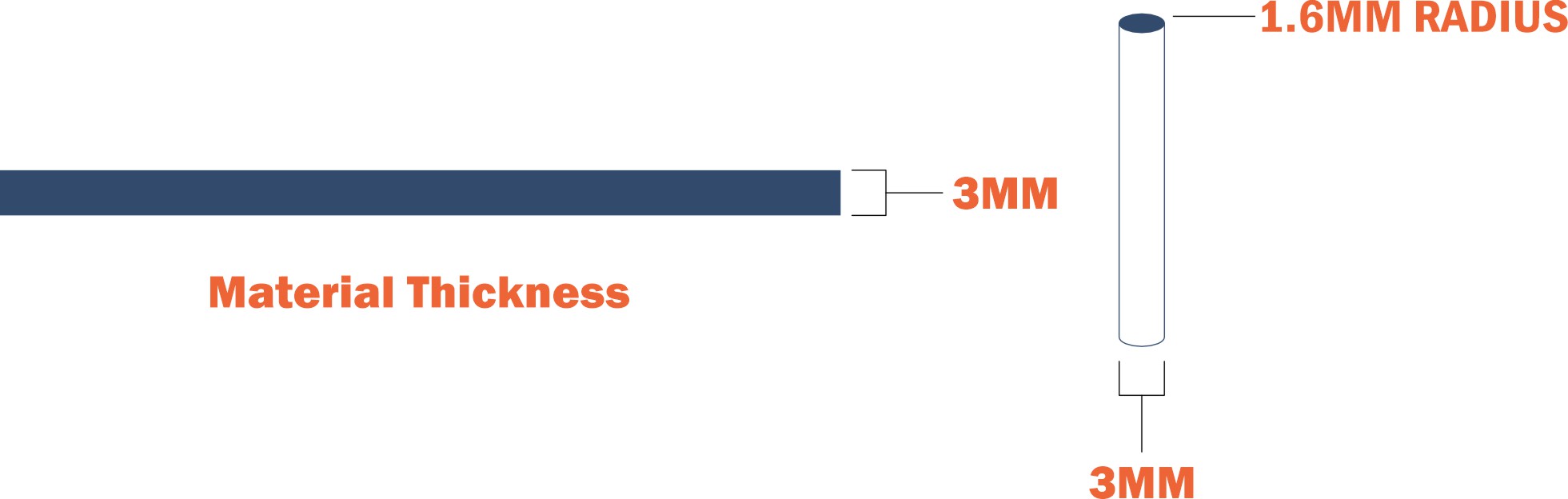
For composite materials, we use a CNC chip-subtractive method (2-dimensional CNC flatbed machining) to cut your parts. We use a 3MM bit, so please allow for a radius of 1.6MM on all internal geometry and a minimum hole size of 3MM
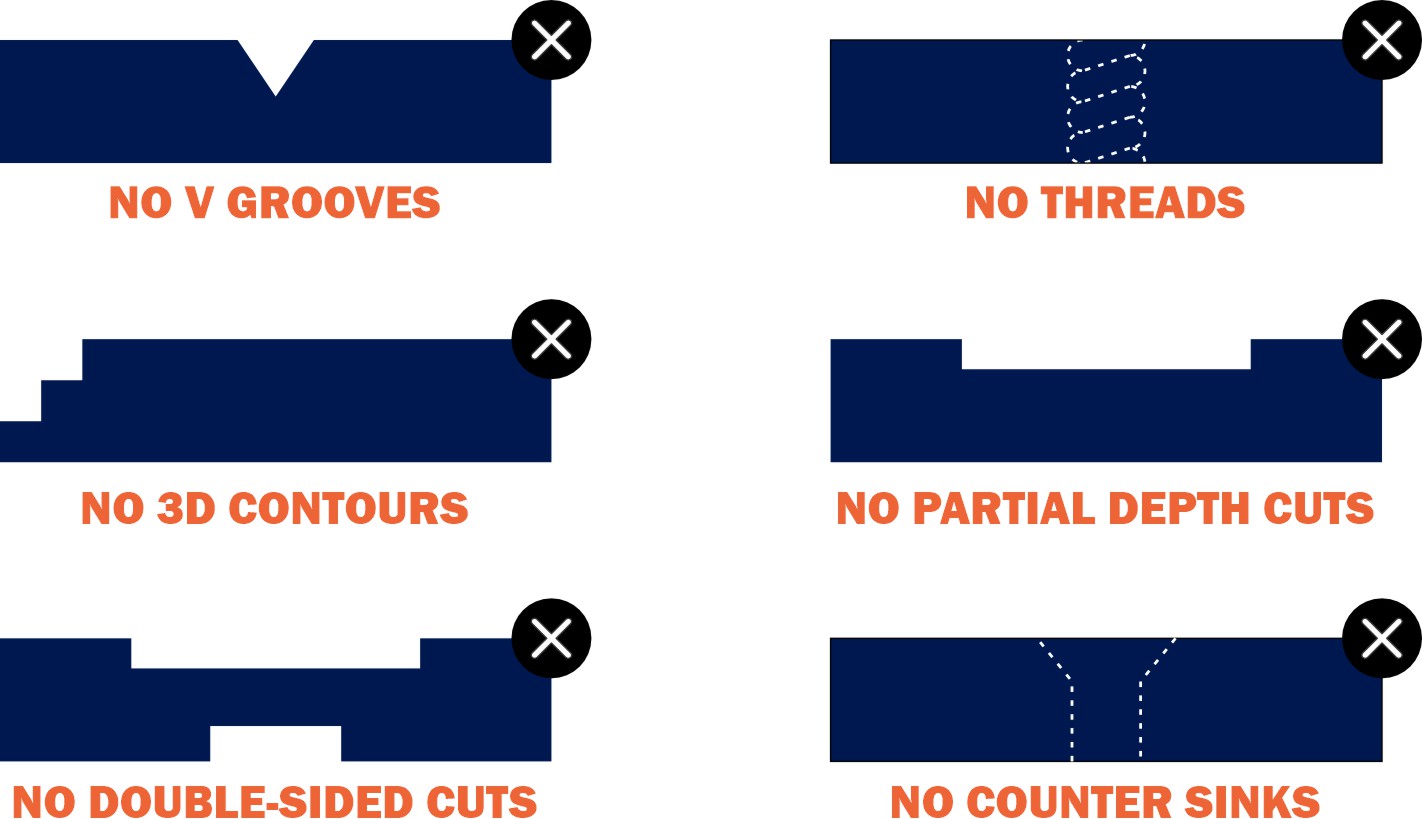
BASIC 2-DIMENSIONAL, PERPENDICULAR CUTS
- No V-groves
- No Threads
- No 3D Contours
- No Partial Depth Cuts
- No Double-Sided Cuts
- No Counter Bores
Please note: Student Version' lettering is automatically ignored by our systems. If you are using SolidWorks as a student, there's no need to worry.
MINIMUM AND MAXIMUM PART DIMENSIONS
For composite materials, we limit the minimum and maximum part sizes to ensure the quickest
and most efficient CNC machining.
Minimum part size:
• 1” x 2”
Maximum part size:
• 44” x 23” (Delrin)
• 44” x 30” (ABS, ACM, HDPE, MDF, Plywood, and UHMW)
Refer to our part sizing chart for overall size limitations for cutting by material.
CNC ROUTER TABS
All parts machined using the CNC router will have small fixturing
tabs left on the edges. These tabs ensure your parts stay
secure during the manufacturing process.
Tabs will be approximately 0.1875″ wide and half the thickness of
your chosen material. These tabs can be easily sanded down and
will not affect your final design.
If you have further questions, refer to our guide on using
fixture tabs in CNC machining.
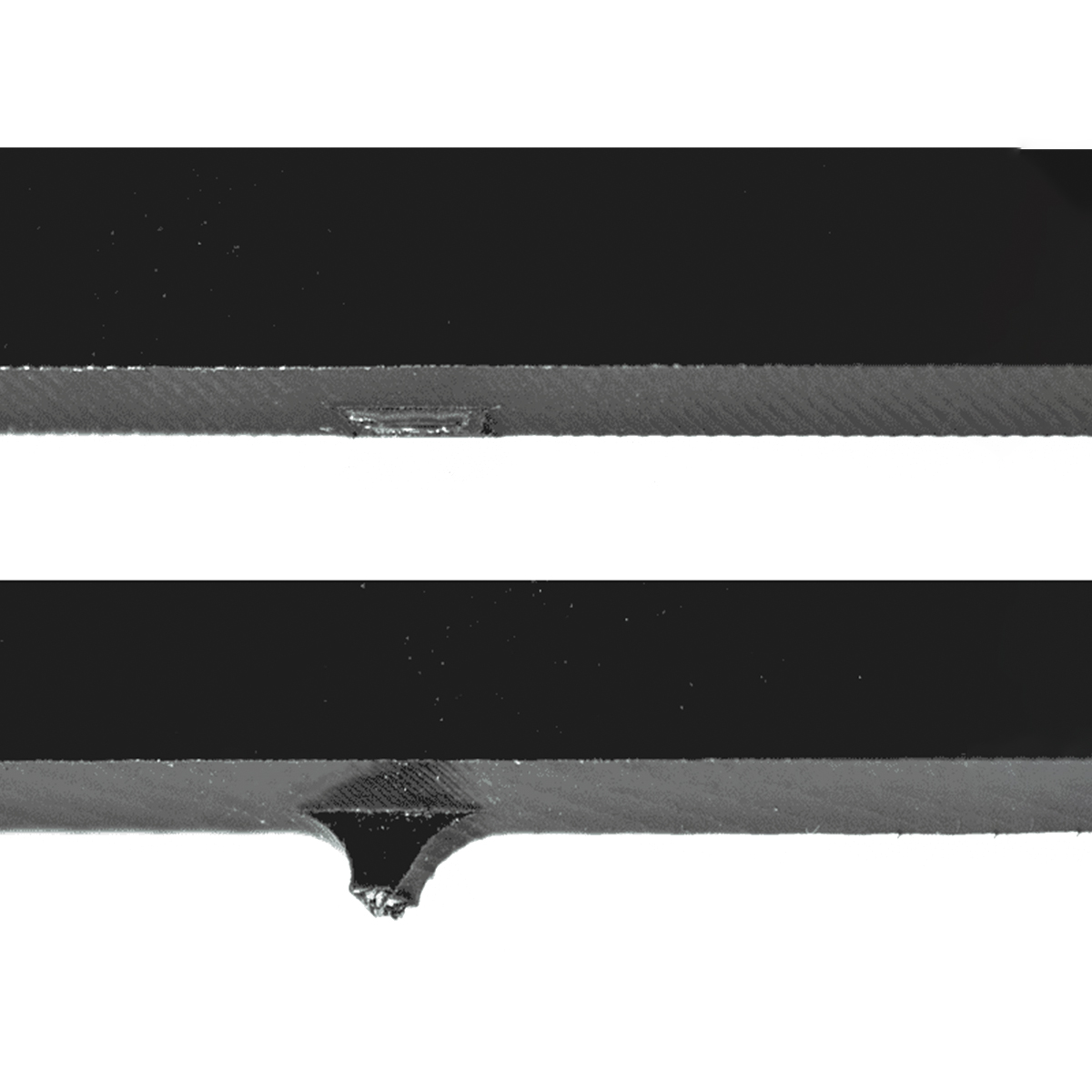
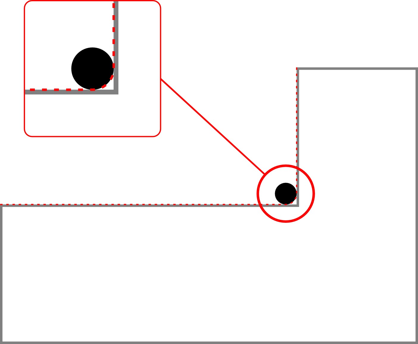
INTERNAL GEOMETRY CONSIDERATIONS
Inside angles (acute angles) will have a slight radius due to the round cutting tool. This radius will be 0.063″, corresponding to the tool’s 0.125″ diameter.
Outside corners are unaffected, but tooling limitations prevent us from producing perfectly square or sharp inside corners.
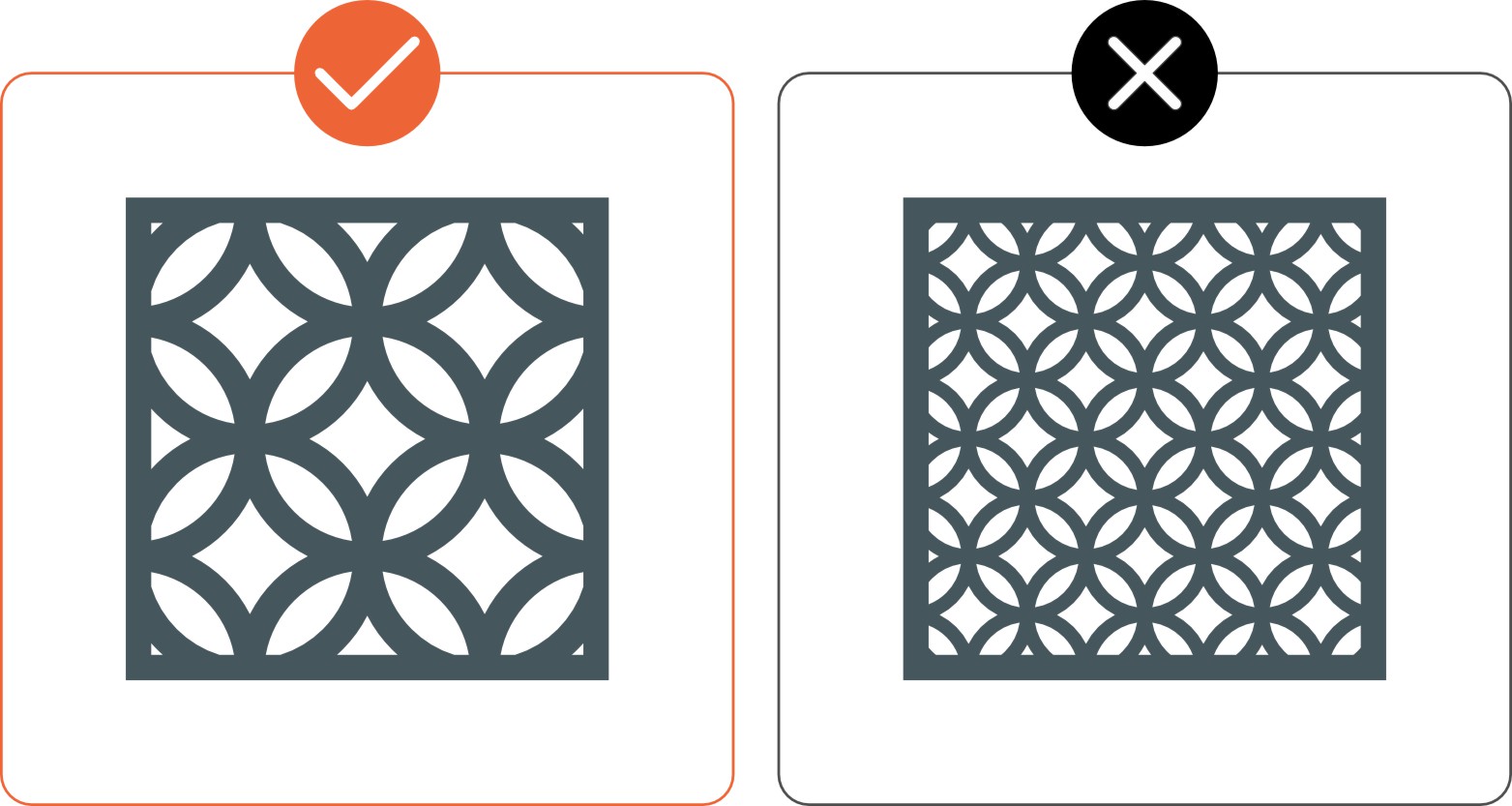
CONSIDERATIONS FOR MATERIAL REMOVAL
AND DESIGN DENSITY
Parts requiring extensive material removal may be impractical to produce. Grills, grates, and perforated patterns are not recommended and may be rejected.
We recommend removing no more than 50% of the material from any part. Removing more increases the risk of the part shifting during cutting, which can cause damage.
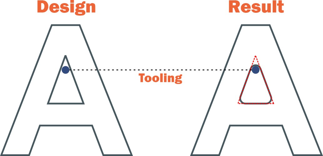
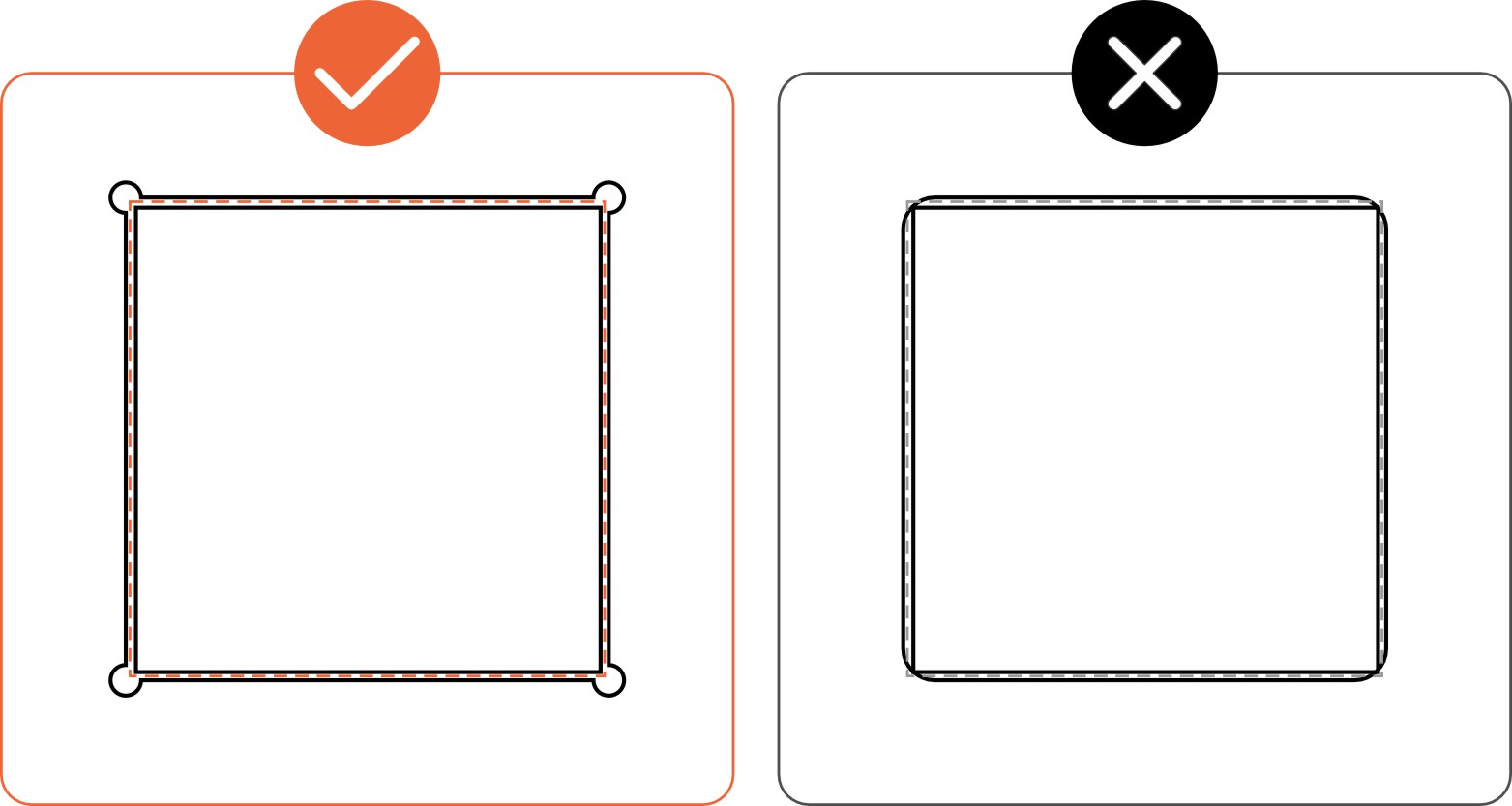
USING DOGBONE FILLETS TO ACHIEVE SQUARE CORNERS
If you have experience designing in CAD, you are likely familiar with standard fillets. However, you might be less familiar with a type of fillet commonly used in CNC milling: the 'Dogbone' fillet.
A standard fillet reduces the sharpness of corners, which can be modified with either a chamfer or a curve.
The solution: Dogbone fillets!
If you have experience designing in CAD, you are likely familiar with standard fillets. However, you might be less familiar with a type of fillet commonly used in CNC milling: the 'Dogbone' fillet.
A standard fillet reduces the sharpness of corners, which can be modified with either a chamfer or a curve.
Ready, let’s go!
With this knowledge, you are ready to start designing your parts for CNC milling. If you have any questions, feel free to contact our support team.
Pre-Flight Checklist
- Ensure your file is in an accepted format (2D: .dxf, .dwg, .ai, .eps; 3D: .step, .stp)
- All holes and cutouts are at least 50% of the material's thickness for laser cut parts
- All holes and cutouts are at least 0.070” for most waterjet cut parts
- All holes and cutouts are at least 0.125” for all CNC routed parts
- Ensure the file is created at a 1:1 scale, preferably in inch or millimeter units
- Ensure all objects are on the same layer
- Remove all stray points, duplicate lines, empty objects, and text areas
- Ensure all shapes are fully enclosed with no open contours
- Ensure all shapes are united, combined, or merged
- Convert all text to outlines or paths
- Ensure cut-out text (reversed text) has bridges or has been stencilized

Validate your login